Current sampling Hall sensor device

A hall sensor and current sampling technology, which is applied in the direction of measuring device, voltage/current isolation, measuring current/voltage, etc., can solve the problems of low sampling accuracy and small sampling range, and achieve the goal of improving measurement accuracy and reliability Effect

Active Publication Date: 2010-03-24
BYD CO LTD
View PDF0 Cites 11 Cited by
  • Summary
  • Abstract
  • Description
  • Claims
  • Application Information

AI Technical Summary

Problems solved by technology

[0005] The inventors of the present invention have found that the current Hall sensor device only includes a Hall sensor with a single range, so that when a Hall sensor with a large range is used to sample a small current, the sampling acc

Method used


Image

  • Current sampling Hall sensor device
  • Current sampling Hall sensor device
  • Current sampling Hall sensor device

Examples


Embodiment Construction

[0011] The present invention will be further described below in conjunction with the accompanying drawings.

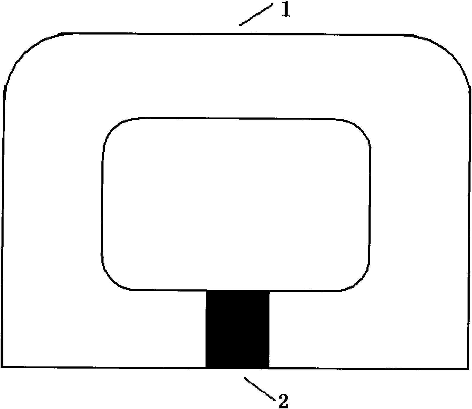
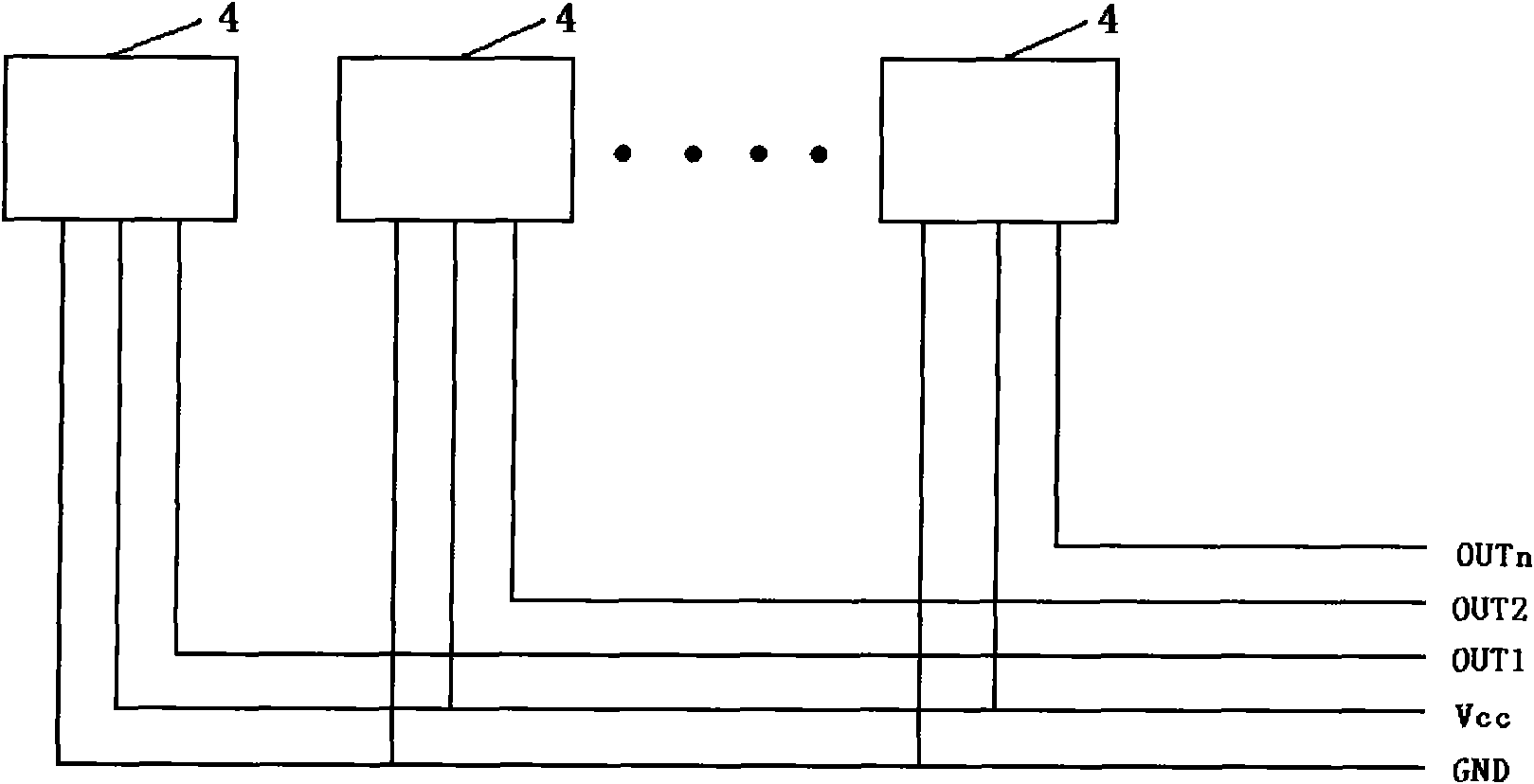
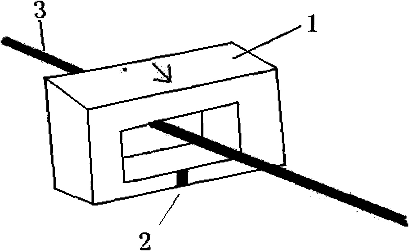
[0012] The current sampling Hall sensor device provided by the present invention, such as figure 1 As shown, the device includes a magnetizer 1 and a Hall sensor 2, the magnetizer 1 is annular with an opening, and the Hall sensor 2 is located in the opening, wherein the Hall sensor 2 includes a plurality of Hall chips 4 ( See figure 2 ), the multiple Hall chips 4 have different ranges and are connected in parallel with each other.

[0013] The device may also include a printed circuit (PCB) board (not shown), the printed circuit board is placed in the opening of the magnetic conductor 1, and the printed circuit board is used to connect a plurality of Hall chips 4, and the printed circuit board has A plurality of lead terminals are respectively a power supply terminal Vcc, a ground terminal GND, and a plurality of output terminals OUT1, OUT2 . . . OUTn. The pluralit...


PUM


Abstract

The invention relates to a current sampling Hall sensor device, comprising a magnetizer (1) and an Hall sensor (2), wherein, the magnetizer (1) is in a ring shape with an opening; the Hall sensor (2)is positioned in the opening and comprises a plurality of Hall chips (4) which have different measuring ranges and are connection with each other in parallel. The device of the invention can ensure the ranges of current sampling and can improve the accuracy of current sampling.

Description

technical field [0001] The invention relates to the field of current sampling, in particular to a current sampling Hall sensor device. Background technique [0002] The Hall effect is widely used in many fields of science and technology today, such as measurement technology, electronic technology, automation technology, etc. In recent years, when sampling the detection current, a Hall sensor device using the principle of the Hall effect is also often used for measurement. An existing Hall sensor device for current sampling includes a magnetizer with a through hole and a Hall sensor built in the magnetizer. The detection current passes through the through hole of the magnetizer through the power line, and a magnetic field will be generated in the magnetizer. The magnetic field is added to the Hall sensor in the magnetizer, and a current is passed to the input end of the Hall sensor, and a magnetic field will be generated at the output end. The Hall current can indirectly me...

Claims


Application Information

Patent Timeline
IPC IPC(8): G01R15/20G01R19/00
Inventor 彭应葱张朕清
Owner BYD CO LTD
Why Eureka
Try Eureka