Powder feeder, powder filling and packaging machine, and method of manufacturing powder package

A technology for supplying devices and filling packages, which is applied in the directions of automatic packaging control, packaging, and packaging protection. It can solve the problems of many wrong actions, difficulties, and large errors, and achieve the effect of realizing actions and suppressing wrong actions.

Inactive Publication Date: 2010-03-24
MITSUBISHI GAS CHEM CO INC
View PDF1 Cites 5 Cited by
  • Summary
  • Abstract
  • Description
  • Claims
  • Application Information

AI Technical Summary

Problems solved by technology

[0007] However, these methods have large errors due to variations in the bag-making properties of individual powder packages and differences in powder filling shapes due to vibrations. If the sensitivity is increased, there will be many erroneous operations.
In addition, in the case of a powder package filled with two types of powders with different volume ratios such as a part of the deoxidizer, there is a disadvantage that it cannot be detected that the powder with a smaller volume ratio is insufficient.
Therefore, it is extremely difficult to know whether all powder packages are filled with the correct amount of powder

Method used


Image

  • Powder feeder, powder filling and packaging machine, and method of manufacturing powder package
  • Powder feeder, powder filling and packaging machine, and method of manufacturing powder package
  • Powder feeder, powder filling and packaging machine, and method of manufacturing powder package

Examples


no. 1 approach

[0051] First, a powder supply device and a powder filling and packaging machine according to a first embodiment of the present invention will be described with reference to the drawings.

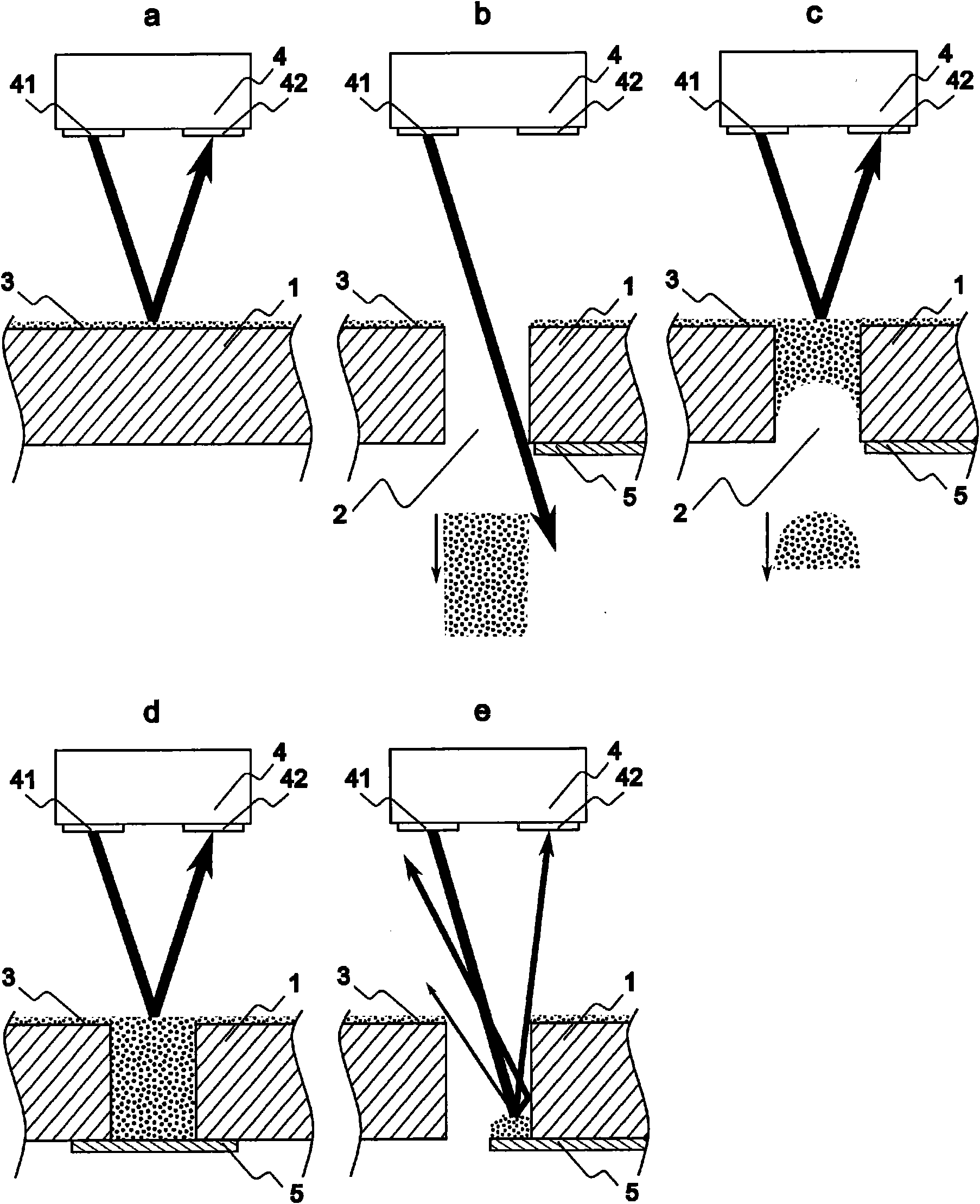
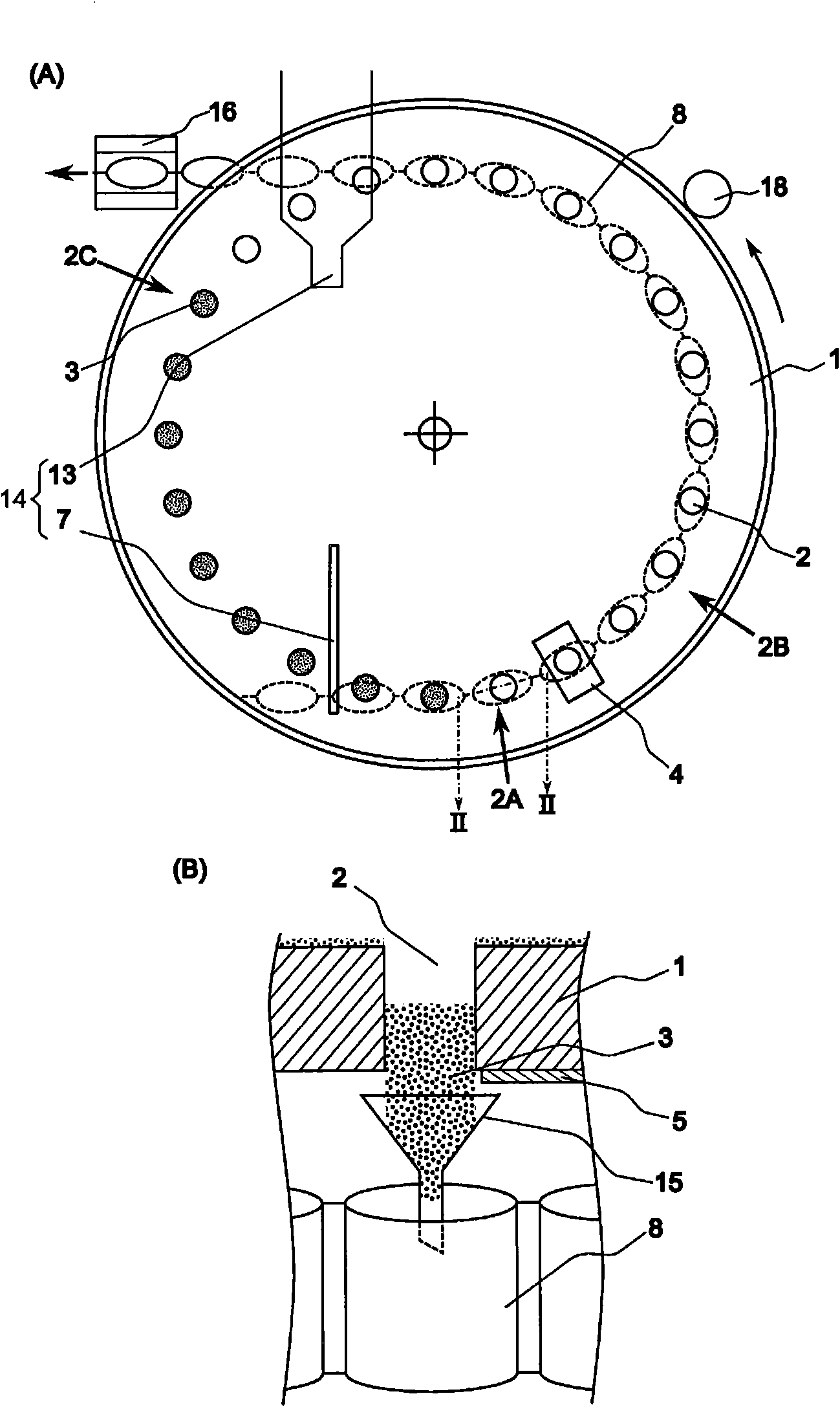
[0052] figure 1 It is a schematic cross-sectional view illustrating the state of filling and dropping powder into the hole of the plate-shaped part of the member, and explaining the state of light emission and light reception by the optical sensor (indicated by arrows). figure 2 It is a schematic diagram explaining the operation of a powder supply device and a powder filling and packaging machine using a rotary motion member. figure 2 A is a top view, figure 2 B is figure 2 Section view of line II-II in A.

[0053] Such as figure 2 As shown, the powder supply device includes: a component 1 with a hole 2 , a motion mechanism 18 for moving the component in a plane, an opening and closing part 5 , a powder filling part 14 , and an optical sensor 4 . In addition, the powder filling and...

no. 2 approach

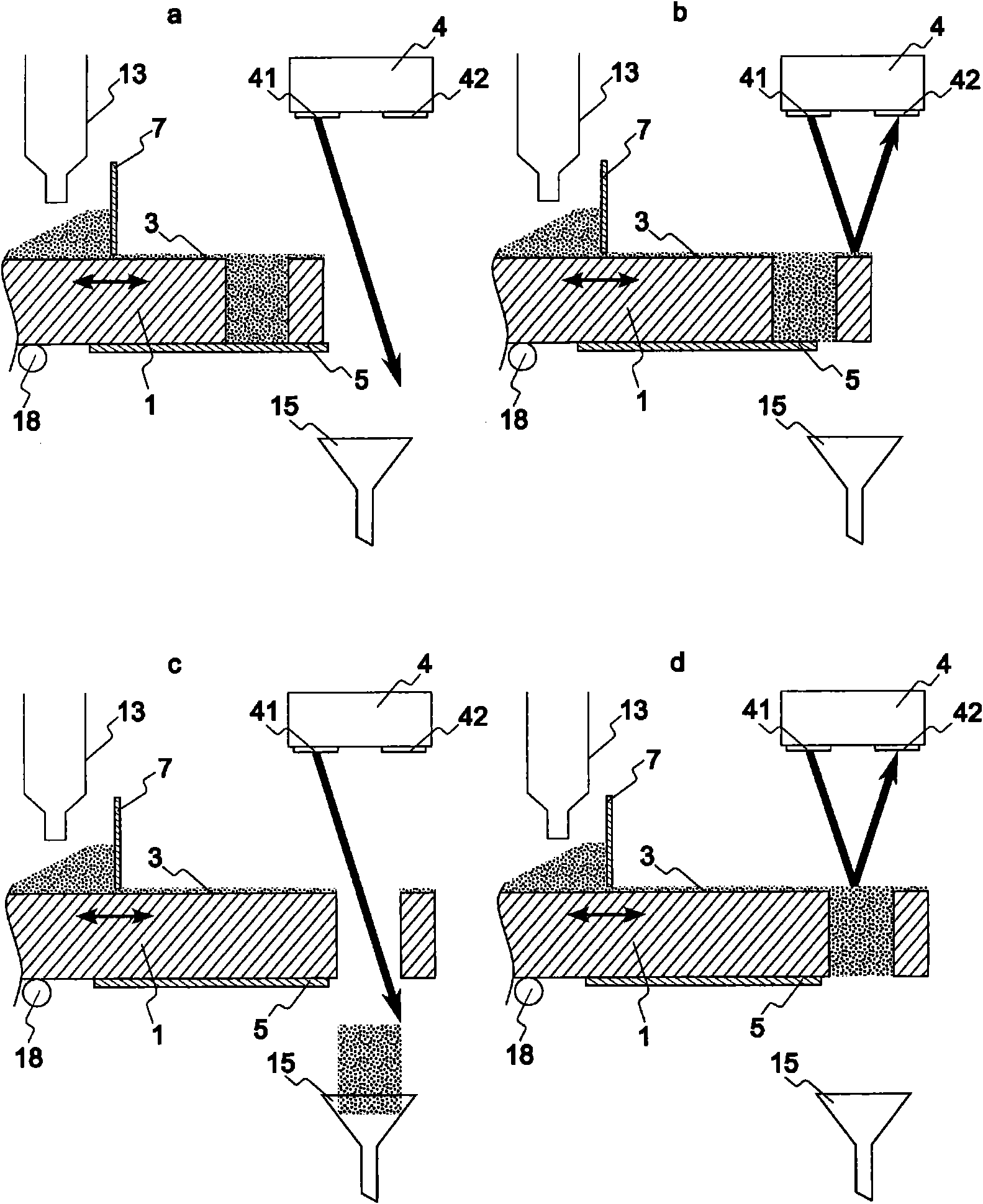
[0103] image 3 It is a diagram showing a powder supply device and a powder filling and packaging machine as the second embodiment of the present invention. When describing this embodiment, the same parts as those in the already described embodiment are denoted by the same reference numerals, and redundant ones are omitted. illustrate. The powder supply device and the powder filling and packaging machine according to the present embodiment will be described with respect to filling and dropping of the powder filling and packaging machine using a reciprocating plate-shaped member. In the present embodiment, the member 1 has a plate shape as a whole, so the member 1 is also called a plate member 1 . and, image 3 is a schematic cross-sectional view, and the optical sensor 4 is arranged directly above the position where the powder 3 falls.

[0104] image 3In a, the lower opening of the hole 2 is blocked, and the plate member 1 provided with the hole 2 functioning as a measuri...

Embodiment 1

[0119] This example uses figure 2 The powder filling packaging machine shown in the first embodiment whose basic structure is shown in FIG. However, the installation position of the kinematic mechanism 18 is different. In addition, in this embodiment, the member 1 used the plate member which has the hole 2 which each passes through on two concentric circles of an inner circle and an outer circle on the main surface. There are 24 through holes 2 on the inner circle and the outer circle respectively. The diameter of the through hole 2 for the inner circle is about 3mm, and the diameter of the through hole for the outer circle is about 8mm. components. Here, the powder filling unit 14 capable of measuring two types of powder is arranged for the inner circle and the outer circle, and forms a powder filling and packaging machine for the deoxidizer.

[0120] The louver opening and closing cam is provided in such a way that after passing through the metering scraper 7, the louver...


PUM


Abstract

Provided are a powder feeder that operates at high speed and in which erroneous operation is suppressed, a powder filling and packaging machine, and a method of manufacturing a powder package. ¢MEANSFOR SOLVING THE PROBLEMS! The powder feeder includes a member (1) having a plate-like part in which through holes (2) are formed, a motion mechanism (18) for moving the member (1) so that the upper openings of the holes (2) move on a specified movement path, opening / closing members (5) for opening and closing the lower openings of the holes (2) as the member (1) moves, a powder filling part (14) for placing, in a predetermined segment of the movement path, a specified amount of powder (3) into the holes (2), and a sensor (4) installed over the movement path in its portion other than the predetermined segment and continuously monitoring the movement path on the plate-like part.

Description

technical field [0001] The present invention relates to a powder supply device that monitors with fewer false detections of dropping failures in which a predetermined amount of powder does not drop from the measuring hopper when various powders are supplied using the measuring hopper, and relates to filling the powder into a packaging bag and A sealed powder filling and packaging machine, and a method for manufacturing a powder package. Background technique [0002] Various medicines or pesticides, fine sugar and other seasonings, deoxidizers with iron powder or easily oxidizable compounds as the main raw material, and other powders, so that the specified amount of the powders can be packed in small bags made of paper or plastic The commodity form is widely known. Generally, when packaging, a powder filling packaging machine is usually used for automation. The powder filling packaging machine introduces the powder into the packaging bag through a hopper after measuring a s...

Claims


Application Information

Patent Timeline
Patent Type & Authority Applications(China)
IPC IPC(8): B65B1/30B65B57/10
CPCB65B1/363B65B57/10B65B1/30
Inventor 片田茂行郡司信雄川口広腾大泽昌彦畠山秀利
Owner MITSUBISHI GAS CHEM CO INC
Why Eureka
Try Eureka