Housing integrated in a wall for receiving sliding doors or windows

A technology of screen window and load-bearing structure, applied in the direction of door/window protection device, window/door, wing sash arrangement, etc., can solve the problem of occupying useful space and so on

Inactive Publication Date: 2010-03-24
马里奥·科莱拉
View PDF3 Cites 3 Cited by
  • Summary
  • Abstract
  • Description
  • Claims
  • Application Information

AI Technical Summary

Problems solved by technology

However, all known solutions have the disadvantage of not being able to incorporate into conventional masonry structures, with the attendant disadvantage of taking up a lot of useful space in the home

Method used


Image

  • Housing integrated in a wall for receiving sliding doors or windows
  • Housing integrated in a wall for receiving sliding doors or windows
  • Housing integrated in a wall for receiving sliding doors or windows

Examples


Embodiment Construction

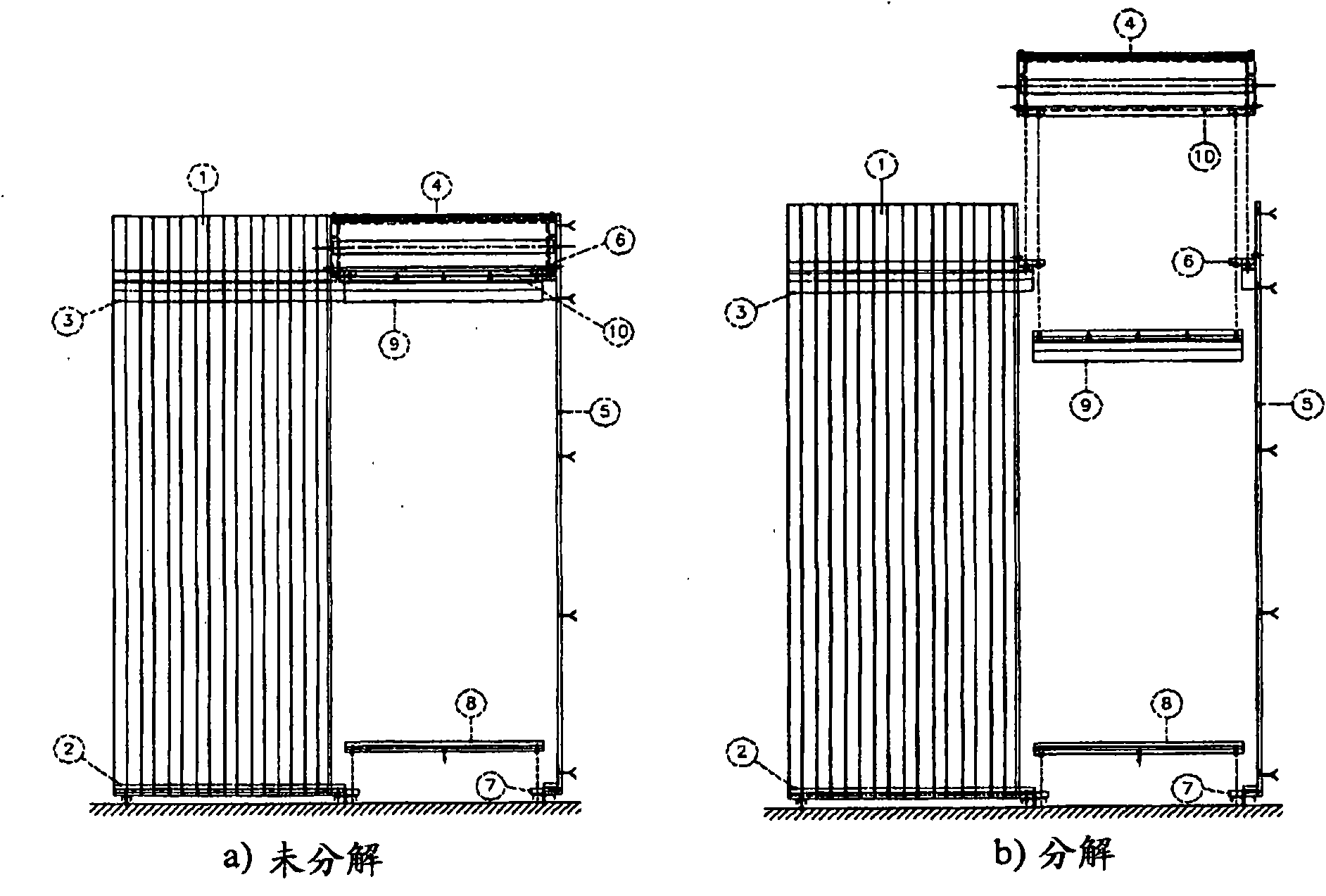
[0017] · figure 1 An assembled view of the non-conductive box is shown in figure a) and figure b), which figure a) is not exploded so that the invention can be seen as a whole from the front, while figure b) is an exploded view, which is useful for identifying the following different Components are useful, such as: non-conductive box 1, a single column 5, the channel or outlet of the column 5 limiting frame; top rail 3, the height of the channel space is limited by the top rail 3, and the self-propelled profile 9 of the top rail is connected to Thereon; a sill 2, in a metal profile, defining the structure of the bottom part, to which a self-propelled bottom or sill profile 8 is attached; a bottom U-bolt 7, to which the sill 2 is fixedly attached on the U-bolt 7; and the top bolt 6 to which the non-conductive roller shutter box 4 is fixedly attached, said shutter box 4 containing the external screen 10 on the upright 5; the other two Supports, the two supports on the non-condu...


PUM

PropertyMeasurementUnit
Thicknessaaaaaaaaaa
Thicknessaaaaaaaaaa
Thicknessaaaaaaaaaa

Abstract

The invention provides a housing integrated in a wall for receiving sliding doors or windows, which comprises a non-conducting box. The housing is mounted in line with the conventional external perimeter masonry. The top of the non-conducting box is attached to the soffit of a floor and is connected with the bottom of a self-bearing wall through a sill in metallic profile. The top of the self-bearing wall is connected with the housing through a guide track. One end of the metallic profile sill is provided with a U-bolt for the connection of the self-propelled sill profile. The top guide track is connected with the self-propelled profile in the passage space. A shutter box (4) contains the winding of the external screen on a roller, which is also formed from two insulating walls and has a minimum total thickness of 30 cm. The housing also comprises a single upright, opposite the non-conducting box, for defining the passage space is made with metallic profile, suitably shaped, a minimum of 30 cm deep and equipped at the ends with a top U-bolt and with a bottom U-bolt. The top U-bolt is used for connection to the non-conducting rolling shutter box and to the tail U-bolt of the top guide track, whereas the bottom U-bolt is used for the fixed connection of the self-propelled sill profile of the passage space.

Description

technical field [0001] The present invention relates to an outer frame intended primarily for use in residential building products, comprising within the outer frame a number of finished products: insulated load-bearing structures, screens, gratings, mesh screens, windows or glazed openings and Awning curtains. The peculiarity of the invention is that these finished products are all still installed in the usual 30 cm thick perimeter wall. Background technique [0002] In the state of the art, different embodiments of similar articles are known which integrate other functions or finished articles within them. These manufactured products are widely used in construction. For example, European Patent Application No. EP 0 132 779 relates to a frame and features a number of prefabricated accessories with which the frame is manufactured. On the other hand, US Patent Application No. 0 142 596 relates to a window having multiple layers, one of which is a blind. The blinds consist...

Claims


Application Information

Patent Timeline
IPC IPC(8): E06B3/46
CPCE06B9/54E06B9/04E06B3/4654E06B9/17007
Inventor 马里奥·科莱拉
Owner 马里奥·科莱拉
Why Eureka
Try Eureka