
Pneumatic pressurizing cradle holding pipe and holding mounting mechanism

A technology of pneumatic pressurization and installation mechanism, applied in spinning machine, textile and papermaking, drafting equipment, etc., can solve the problems of inconsistent installation angle of six-sided twist cradle, cumbersome processing, cumbersome installation procedures, etc. The effect of installing labor intensity, simplifying pressure regulation procedures, and solving pressure regulation difficulties

Inactive Publication Date: 2015-03-04
四川成发普睿玛机械工业制造有限责任公司
View PDF9 Cites 0 Cited by
  • Summary
  • Abstract
  • Description
  • Claims
  • Application Information

AI Technical Summary

Problems solved by technology

Their disadvantages are: 1. Due to the large adjustment gap between the upper and lower fixing card end faces of the cradle, during the installation, pressure regulation and fastening process of the cradle, the screw-in length of the front and rear screws is inconsistent, and the positioning protrusion There is a certain angular rotation space with the positioning hole, the cradle can rotate along the center of the holding tube, and the angular position cannot be controlled consistently; in order to adjust the rated working pressure of the cradle, when tightening the front and rear screws, the tightening force is usually inconsistent , the upper and lower installation decks of the cradle are deformed due to excessive force, which makes the installation procedure of the lever-type pneumatic pressurized cradle cumbersome and difficult to adjust the rated pressure; the circular holding tube needs to process the positioning groove (installed on the holding tube seat , to prevent the round tube from angular rotation) and the positioning hole (positioned with the next fixed card bump), holding the tube seat needs to process the positioning key that matches the positioning groove of the holding tube, the processing is cumbersome and the precision is high
2. Due to the high processing difficulty of the hexagonal holding tube, the twist degree of the six planes is not easy to guarantee, and the twist degree of the six sides is out of tolerance, which leads to inconsistent installation angles of the cradle, and the cradle will also have excessive pressure or the pressure cannot reach the working pressure. Happening
3. The circular holding tube or hexagonal holding tube will produce deflection and deformation when the cradle is pressurized, which will affect the consistency of the cradle’s pressure.

Method used


Image

  • Pneumatic pressurizing cradle holding pipe and holding mounting mechanism
  • Pneumatic pressurizing cradle holding pipe and holding mounting mechanism
  • Pneumatic pressurizing cradle holding pipe and holding mounting mechanism

Examples


Embodiment 1

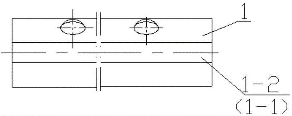
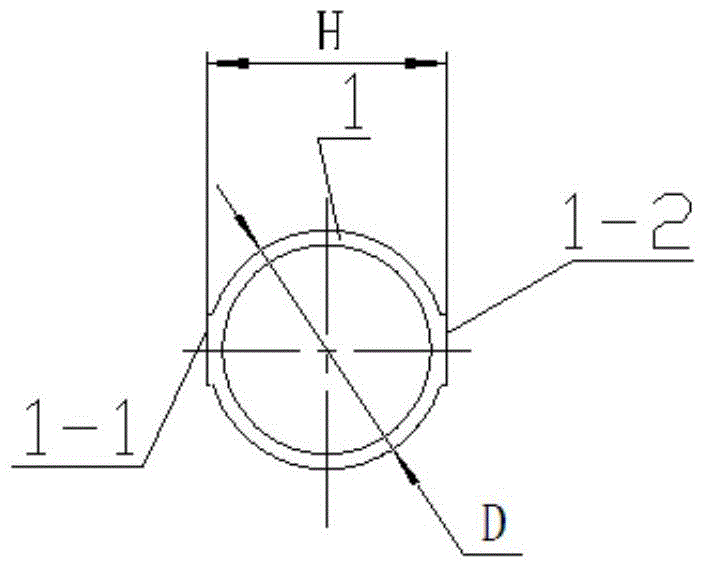
[0020] The pneumatic pressurized cradle holding tube described in this embodiment is as follows: figure 1 , figure 2 As shown, a special-shaped pipe fitting is provided with a left positioning plane 1-1 on the left outer wall of the round pipe and a right positioning plane 1-2 on the right outer wall. The left positioning plane and the right positioning plane are symmetrical to the axis of the special-shaped pipe fitting. The distance H between the positioning plane and the right positioning plane is equal to the outer diameter D of the circular tube forming the holding tube, the left positioning plane and the left side outer wall of the circular tube are integral structures, and the right positioning plane and the outer diameter of the circular tube are The right outer wall is an integrated structure.

Embodiment 2

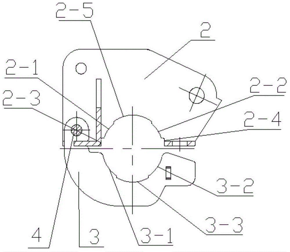
[0022] The grip and installation mechanism of the pneumatic pressurized cradle described in this embodiment is as follows: image 3 , Figure 4 As shown, it includes an upper fixing card 2, a lower fixing card 3 and a holding tube 1. The holding pipe 1 is a special-shaped pipe fitting with the shape and structure described in Embodiment 1; Surrounded by a free arc surface 2-5, a second positioning arc surface 2-2, and a second positioning plane 2-4, the first positioning plane 2-3 and the second positioning plane 2-4 are parallel to each other, between them The distance is equal to the distance H between the left positioning plane 1-1 and the right positioning plane 1-2 of the holding tube, the radius of the first positioning arc 2-1 and the second positioning arc 2-2 are the same and they The radius of is equal to the outer radius of the round tube that forms the holding tube, and the radius of the first free arc surface 2-5 is 1.5mm larger than the outer radius of the roun...


PUM


Abstract

Disclosed is a pneumatic pressurizing cradle holding pipe. The pipe is an abnormal-shaped pipe, a left positioning plane of the abnormal-shaped pipe is arranged on the outer wall of the left side of a circular pipe, a right positioning plane of the abnormal-shaped pipe is arranged on the outer wall of the right side of the circular pipe, the left positioning plane and the right positioning plane are symmetrical along the axis of the abnormal-shaped pipe, the distance H between the left positioning plane and the right positioning plane is equal to the outer diameter D of the circular pipe which forms the holding pipe, the left positioning plane and the outer wall of the left side of the circular pipe are in an integrated structure, and the right positioning plane and the outer wall of the right side of the circular pipe are in the integrated structure. A pneumatic pressurizing cradle holding mounting mechanism comprises an upper fixing clamp, a lower fixing clamp and the holding pipe.

Description

technical field [0001] The invention belongs to the field of pneumatic pressurized cradles in textile machinery, and in particular relates to a holding pipe and a holding installation mechanism of a pneumatic pressurized cradle. Background technique [0002] The existing holding mechanism installed on the lever-type pneumatic pressurized cradle, one is to use a circular holding tube, and there is a positioning hole under the holding tube, and the positioning protrusion of the lower fixing card and the positioning hole of the circular holding tube Cooperate with each other to form angular positioning. The upper and lower fixing cards are connected by two front and rear tangential screws; the other is to use a hexagonal holding tube. The holding tube fits together to prevent angular rotation of the cradle. Their disadvantages are: 1. Due to the large adjustment gap between the upper and lower fixing card end faces of the cradle, during the installation, pressure regulation an...

Claims


Application Information

Patent Timeline
Patent Type & Authority Applications(China)
IPC IPC(8): D01H5/56D01H5/52
CPCD01H5/52D01H5/56
Inventor 俞刚覃俊熊飞牛宝林
Owner 四川成发普睿玛机械工业制造有限责任公司
Learn More