Check patentability & draft patents in minutes with Patsnap Eureka AI!

Housing for a turbomachine

A fluid machinery and casing technology, applied in the field of turbomachinery casings, can solve problems such as steam or hot gas leakage, and achieve the effects of reducing temperature sensitivity, reducing manufacturing costs, and reducing space requirements

Inactive Publication Date: 2010-03-24
ALSTOM TECH LTD
View PDF0 Cites 0 Cited by
  • Summary
  • Abstract
  • Description
  • Claims
  • Application Information

AI Technical Summary

Problems solved by technology

[0006] In the case of monocoques, in addition to the above-mentioned disadvantages that arise when using clamping rings or when using fastening flanges, additional Risk of steam or hot gases escaping into the surroundings

Method used


Image

  • Housing for a turbomachine
  • Housing for a turbomachine
  • Housing for a turbomachine

Examples


Embodiment Construction

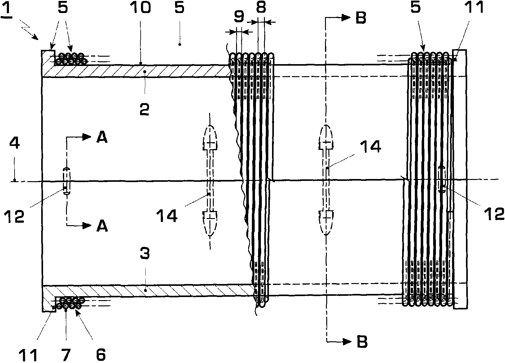
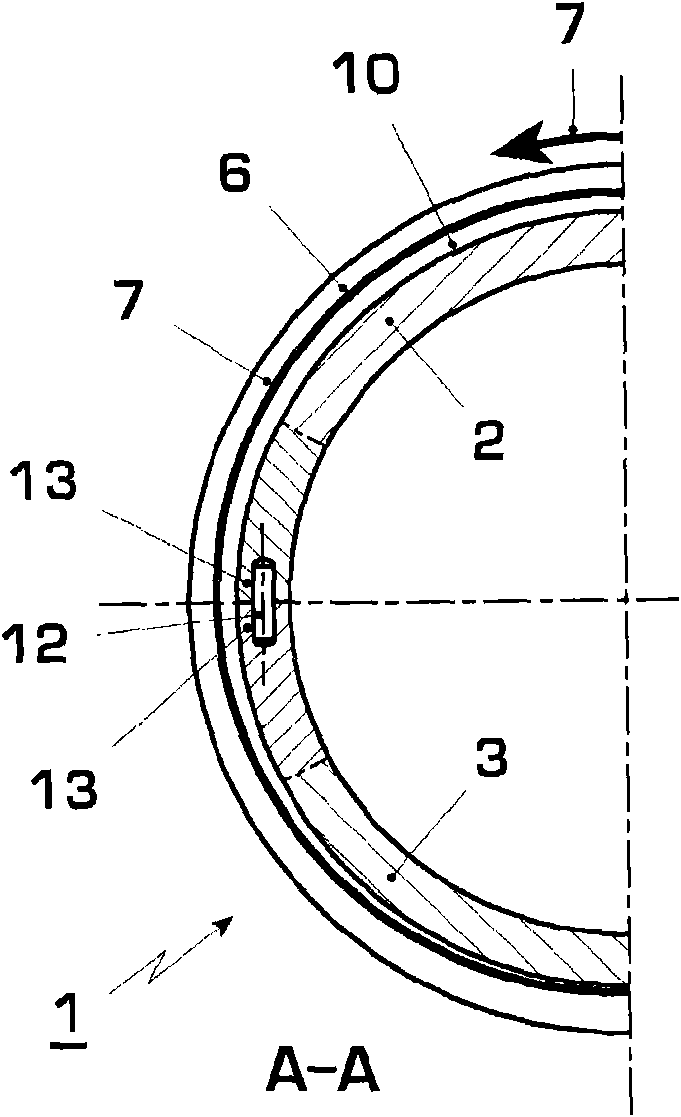
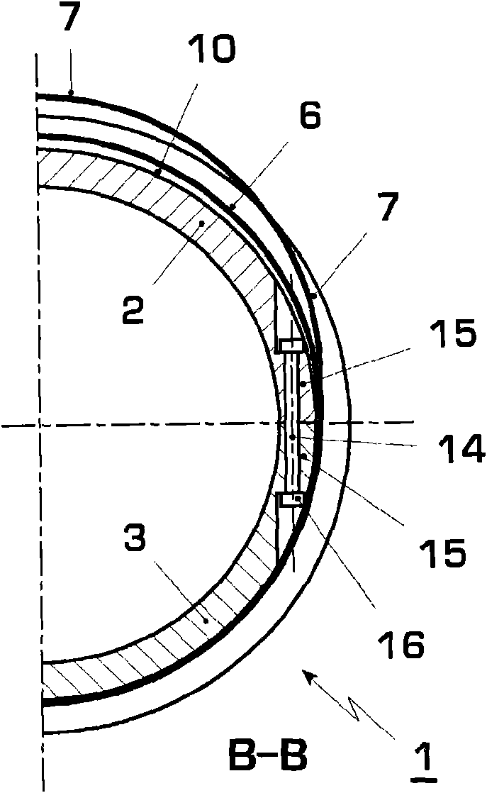
[0026] according to figure 1 , the housing 1 of the turbomachine, whose remaining parts are not shown, comprises two housing halves 2 , 3 , namely in particular an upper housing half 2 and a lower housing half 3 . The two housing halves 2 , 3 bear against one another at an axial boundary 4 , whereby the housing 1 is closed in the circumferential direction. Furthermore, the housing 1 includes a fastening device 5 which is designed in such a way that the two housing halves 2 , 3 can be fixed to each other and can be prestressed relative to each other.

[0027] The aforementioned fastening device 5 has at least one coil 6 formed with at least one guy rope 7 . The coil 6 wraps around the two housing halves 2 , 3 at their outer sides. In this case, the winding takes place in the circumferential direction or helically. The helical winding 6 here expediently has a slope 8 corresponding to the rope thickness or rope diameter 9 . Other slopes 8 are also conceivable. The guyline 7 ...


PUM


Abstract

The present invention relates to a housing (1) of a turbomachine, comprising two housing halves (2, 3) resting one against the other on an axial separating plane (4), and a fastener device (5) for fixing said housing halves (2, 3) to one another and providing said halves with initial tension against one another. In order to improve the fixation of the housing halves (2, 3), the fastener device (5)comprises at least one winding (6) surrounding the housing halves (2, 3), said winding being comprised of at least one tensioning cable (7) made of at least one wire.

Description

technical field [0001] The invention relates to a housing for a turbomachine, in particular a turbomachine. Furthermore, the invention relates to a mounting device (Montagevorrichtung) for the installation (Anbringen) of coils on such housings. Background technique [0002] Fluid machines, in particular turbo machines, such as steam turbines, gas turbines, compressors, water turbines or hydraulic pumps, are subjected to very high pressure loads during operation. In steam turbines, gas turbines and compressors or boosters, additional loads are imposed due to the high temperatures. These loads must be able to be taken up by the housing of the corresponding fluid machine. Housings of this type are generally assembled from two half-shells which abut one another in the region of the axial boundary of the housing. In this case, the axial orientation of the housing is given by the orientation of the rotor of such fluid machines, the axis of rotation of which defines the axial di...

Claims


Application Information

Patent Timeline
Patent Type & Authority Applications(China)
IPC IPC(8): F01D25/24
CPCF01D25/24F04D29/644F04D29/648F04D29/624F04D29/628F04D1/063F04D19/02F04D17/122F01D21/045
Inventor F·巴杰伊M·雷格尔
Owner ALSTOM TECH LTD
Features
  • R&D
  • Intellectual Property
  • Life Sciences
  • Materials
  • Tech Scout
  • Unparalleled Data Quality
  • Higher Quality Content
  • 60% Fewer Hallucinations
Learn More