Design of a group of wind power plants

A station group and wind speed technology, which is applied in the field of wind power station groups, can solve the problems of multi-power, complex control of wind power station groups, and failure to obtain, and achieve the effects of reducing risks, large rotor sweep area, and improving wind power utilization

Inactive Publication Date: 2010-03-24
LM GLASSFIBER
View PDF1 Cites 1 Cited by
  • Summary
  • Abstract
  • Description
  • Claims
  • Application Information

AI Technical Summary

Problems solved by technology

The disadvantage of this strategy is that on the one hand it requires a complex control of each wind power plant group and on the other hand it does not get a considerable amount of electrical energy

Method used


Image

  • Design of a group of wind power plants
  • Design of a group of wind power plants
  • Design of a group of wind power plants

Examples


Embodiment Construction

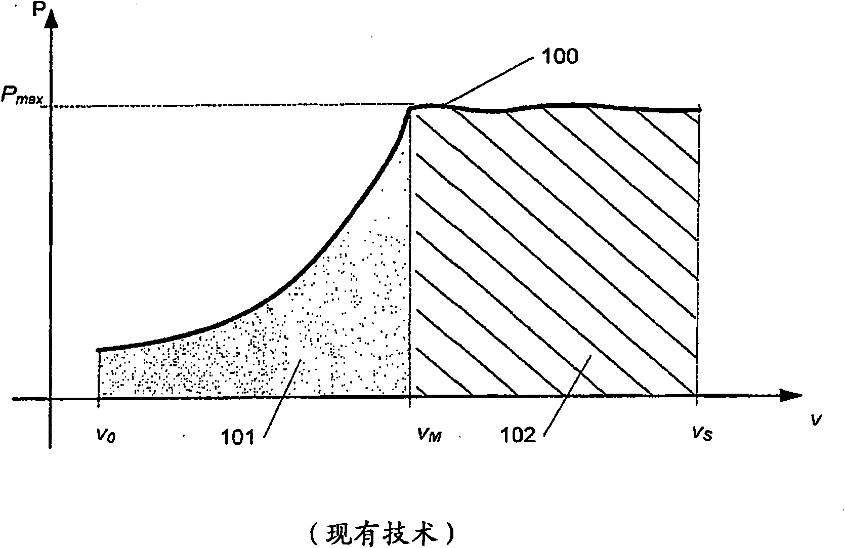
[0031] figure 1 A typical power curve 100 of a wind power plant is schematically shown. The curve shows the generated power P or power output as a function of the wind speed v. A wind power station with a wind speed of V 0 Start to generate power at the initial wind speed, the wind speed V 0 Most of them are of the order of 2-4m / s. The pitch adjustment wind power plant here can slightly change the pitch of the blades and help start the wind power plant. From this point on, the power output increases with increasing wind speed until it reaches the rated wind speed V M , then the wind power station produces the maximum effect P max , the maximum effect P max Also known as power rating. In the area 101 the wind power plant is configured to maximize the power output and throughput of the wind power plant and to optimally utilize the wind energy. The wind energy content increases with the third power of the wind speed, but from a purely physical point of view and a design p...


PUM


Abstract

The present invention relates to a group of wind power plants for positioning in approximately the same wind climate, comprising at least a first and at least a second wind power plant, where the first wind power plant exhibits maximised power output within a first interval of wind speeds, and the second wind power plant is designed to exhibit maximised power output within a second interval of wind speeds which is different from and starting from lower wind speeds than the first wind speed interval to the effect that the total power output of the group of wind power plants is increased at lower wind speeds. Moreover, the invention relates to a method of designing a group of wind power plants in accordance with the above. This can be accomplished eg by designing the supplementary wind powerplant(s) with a larger rotor area and with a lower cut-out wind speed or, alternatively, by using a wind power plant without power-regulating means. Hereby it is accomplished that the power production of the group becomes more uniform and not so dependent on the current wind speed. The smaller power output from the supplementary wind power plants is completely or partially balanced by, on the onehand, the lower production and operating costs of the turbine and, on the other, the higher price on electricity.

Description

technical field [0001] The invention relates to a group of wind power plants, comprising at least a first and at least a second wind power plant, arranged in substantially the same wind environment. Background technique [0002] An electricity network that regulates and serves a region's electricity supply is usually described by its local sources of energy such as coal-fired power stations, hydroelectric power stations, nuclear power stations, wind farms, its users and the corresponding transmission capacity , the transmission capacity moves in and out of the network within the network as well as for electricity import and export. Usually, the different electricity networks are limited to countries, regions or territorial areas, but they are often also defined by geographical and purely practical conditions. An example of such a geographically separated electricity network is Western Denmark, which is currently electrically connected to Norway, Sweden and Germany. The tot...

Claims


Application Information

Patent Timeline
Patent Type & Authority Applications(China)
IPC IPC(8): F03D7/04F03D9/00
CPCY02E10/723F05B2250/80Y02E10/722F05B2240/40F05B2270/32F03D7/028F05B2270/20F03D7/048Y02E10/72
Inventor B·E·彼泽森
Owner LM GLASSFIBER
Why Eureka
Try Eureka