Releasably locking auto-aligning fiber optic connector

A technology of connector components and optical fibers, applied in the direction of connection, connection device parts, instruments, etc., can solve the problems of patient discomfort, catheter removal, etc.

Active Publication Date: 2010-03-24
EDWARDS LIFESCIENCES CORP
View PDF0 Cites 10 Cited by
  • Summary
  • Abstract
  • Description
  • Claims
  • Application Information

AI Technical Summary

Problems solved by technology

Excessive tension on the catheter lead wire or other connecting cable can cause severe patient discomfort, catheter displacement, or worst case removal of the catheter from the patient insertion site

Method used


Image

  • Releasably locking auto-aligning fiber optic connector
  • Releasably locking auto-aligning fiber optic connector
  • Releasably locking auto-aligning fiber optic connector

Examples


Embodiment Construction

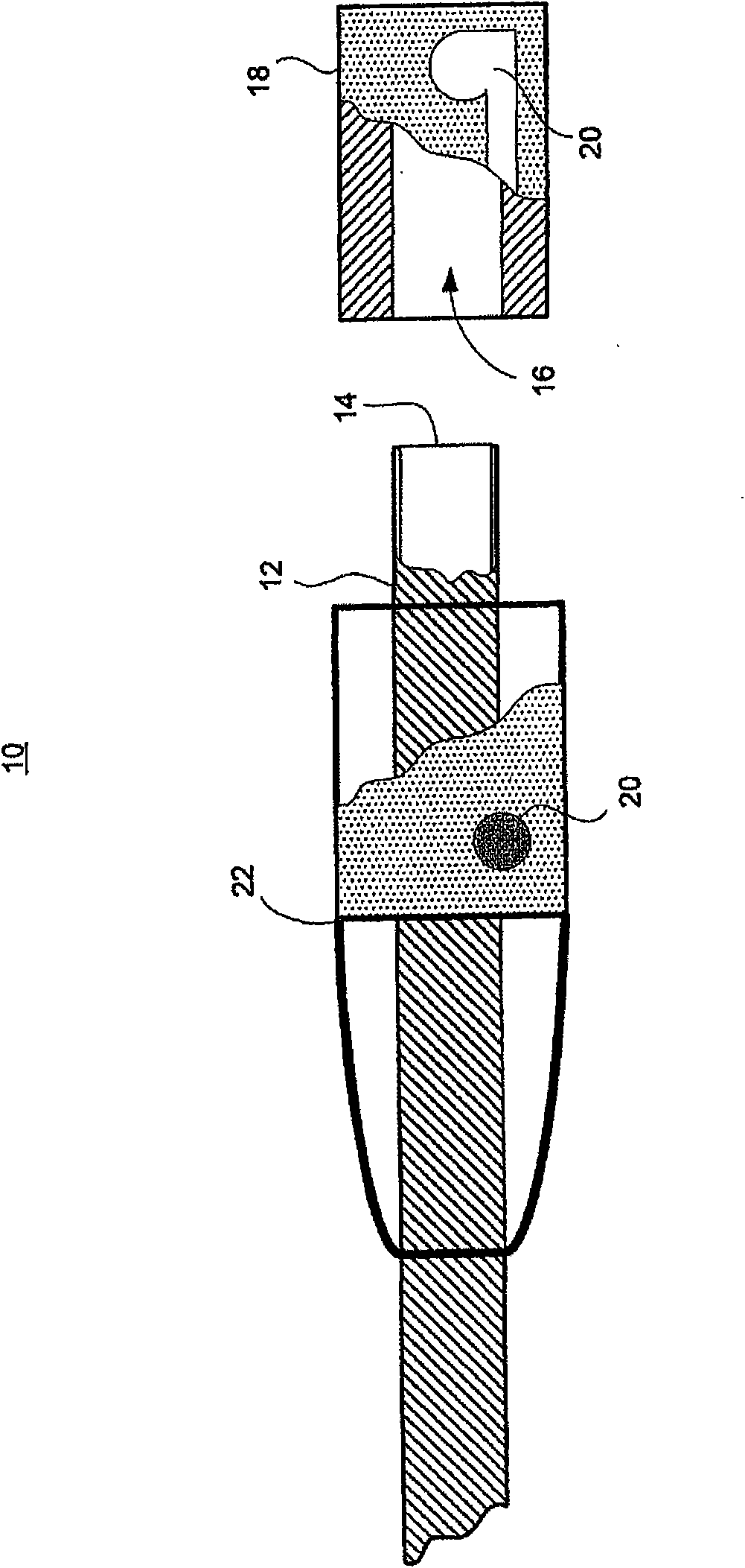
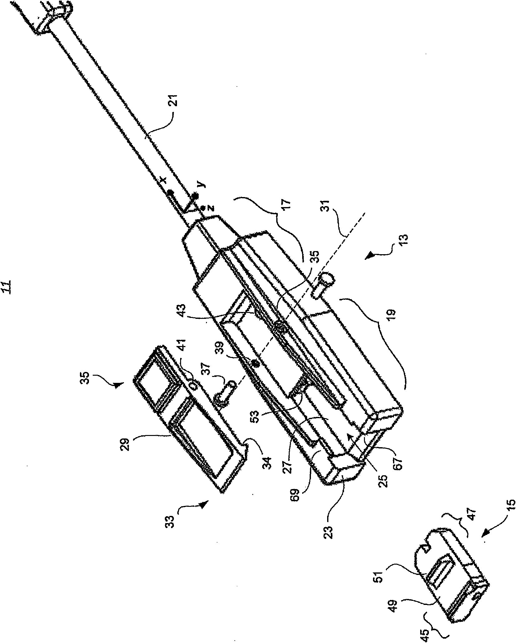
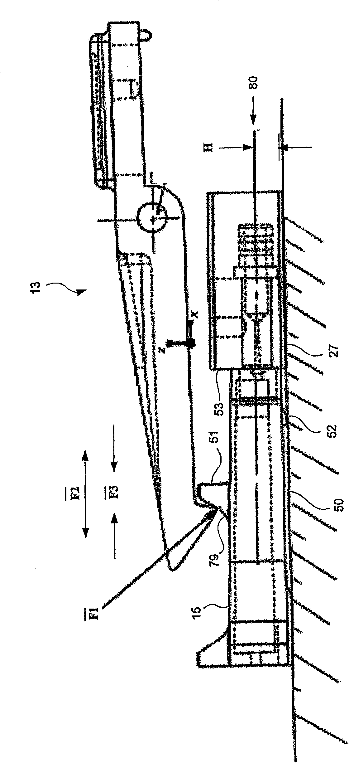
[0019] [0018] The present invention provides a coupling device for medical applications that maintains coaxial alignment of optical connections while allowing easy release from a catheter without interfering with the patient puncture site. figure 2 An isometric view of the connector assembly 11 according to an embodiment of the present invention is shown. Connector assembly 11 includes receptacle 13 and plug 15 . Receptacle 13 and plug 15 may be made of a rigid dielectric material such as molded plastic. Receptacle 13 and plug 15 each terminate signal lines, and when mechanically engaged in coaxial alignment, they collectively couple the signal lines to ensure signal transmission through the coupling header with minimal insertion loss.

[0020] [0019] The receptacle 13 includes a terminating end 17 and a receiving end 19. The termination terminal 17 receives and terminates the signal line 21 . In one embodiment, the signal line 21 is a fiber optic line having one or more f...


PUM


Abstract

A connector assembly couples signal lines for an optical catheter by providing a guided releasable latching mechanism that ensures optimal alignment with only a single vertical dimension under control. A receptacle carrying a first signal line defines a channel for receiving a plug carrying a second signal line, A spring-loaded pawl on the receptacle locks to a retaining bracket on the plug when the plug slides into the channel, imparting a retaining force on the plug, the force having a first component normal to channel and a second component parallel to the channel to maintain the first andsecond signal lines in optimal alignment. The retaining bracket may include a sloped edge to allow for easy release of the pawl in the presence of a release force. The release force may be set to allow disconnection of the assembly without affecting catheter installation or causing patient discomfort.

Description

[0001] Priority claim pursuant to 35 U.S.C. § 119 [0002] [0001] This patent application claims priority to Provisional Application No. 60 / 896,475, filed on March 22, 2007 and assigned to its assignee, which is expressly incorporated herein by reference. technical field [0003] [0002] The present invention generally relates to connectors for fiber optic instruments. More specifically, the present invention relates to a module for coupling an optical instrument to an optical measurement device that can be disposed within a catheter. Background technique [0004] [0003] Optical instruments, such as endoscopic imaging devices, have been used in medical applications for many years. Common techniques for performing minimally invasive imaging include placing the imaging device within a catheter, such as a central venous catheter, which then delivers the imaging device to the desired intravenous location. Because of the space constraints encountered when inserting these devices...

Claims


Application Information

Patent Timeline
Patent Type & Authority Applications(China)
IPC IPC(8): G02B6/38
CPCG02B6/3893H01R13/6275
Inventor M·G·戈登W·D·维斯特
Owner EDWARDS LIFESCIENCES CORP
Why Eureka
Try Eureka