Negative electrode for lithium secondary battery, lithium secondary battery comprising the same, and method for producing negative electrode for lithium secondary battery
A lithium secondary battery and manufacturing method technology, applied in the direction of electrode manufacturing, secondary batteries, battery electrodes, etc., can solve the problems of insufficient strength and insufficient suppression of active material falling off, so as to inhibit self-destruction and improve charge-discharge cycle Excellent performance and cycle characteristics
- Summary
- Abstract
- Description
- Claims
- Application Information
AI Technical Summary
Problems solved by technology
Method used
Image
Examples
Embodiment approach 1
[0074] Hereinafter, a first embodiment of the negative electrode for a lithium secondary battery (hereinafter, simply referred to as "negative electrode") of the present invention will be described with reference to the drawings.
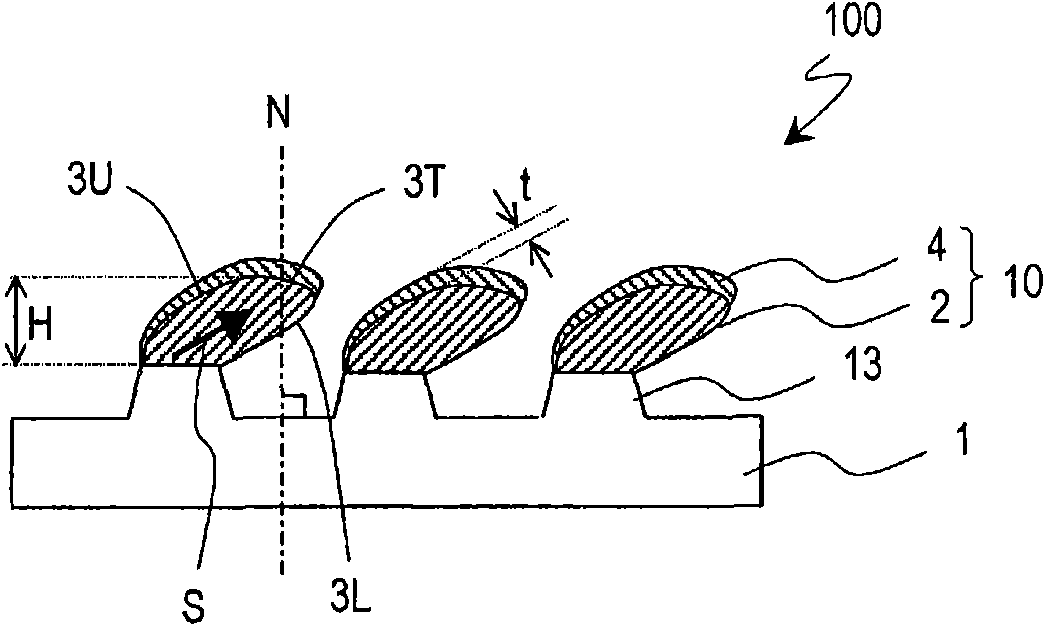
[0075] First refer to figure 1 . figure 1 It is a schematic sectional view of the negative electrode for lithium secondary batteries of this embodiment.
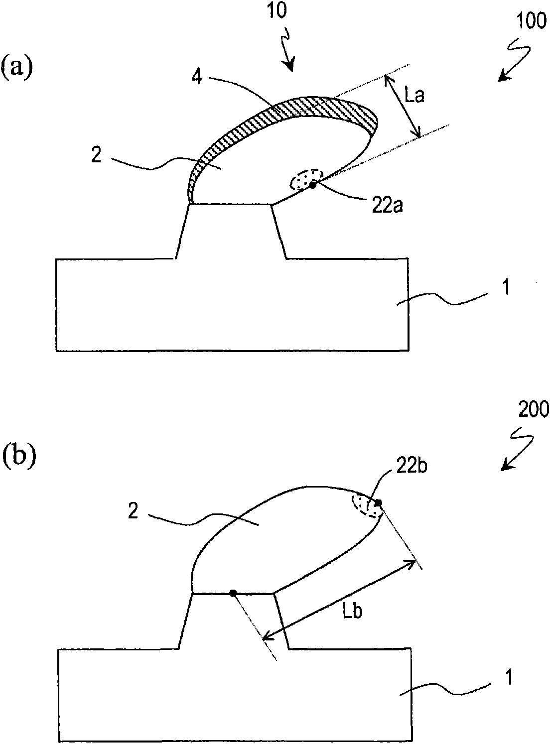
[0076] The negative electrode 100 has: a current collector 1; and a plurality of active material complexes 10 formed on the current collector 1. In the present embodiment, a plurality of protrusions 13 are regularly arranged on the surface of the current collector 1 , and each active material complex 10 is arranged on the corresponding protrusions 13 . Each active material complex 10 extends in a direction protruding from current collector 1 , and has active material body 2 composed of a substance that absorbs and releases lithium; and conductor 4 arranged in contact with active material body 2 ...
Embodiment approach 2
[0143] Hereinafter, a second embodiment of the negative electrode for a lithium secondary battery of the present invention will be described with reference to the drawings.
[0144] First, refer to Image 6 . Image 6 It is a schematic sectional view of the negative electrode for lithium secondary batteries of this embodiment. For convenience, use figure 1 The same constituent elements of the negative electrode 100 shown are denoted by the same reference numerals, and description thereof will be omitted.
[0145] The negative electrode 400 has a current collector 1 and a plurality of active material complexes 20 formed on the surface of the current collector 1 . Each active material complex 20 has an active material body 2 including a plurality of active material parts 2a to 2e, and a conductor 4 including a plurality of conductive parts 4a to 4e. Active material portions 2a to 2e are stacked in this order on the surface of current collector 1, and conductive portions 2a t...
Embodiment 1-1
[0185] In Example 1-1, a copper foil having a plurality of protrusions formed on the surface of a rolled copper foil having a core material thickness of 35 μm by rolling with rolling rolls was used as the current collector. For the copper foil of section 13, the rolling roll is provided with minute recesses on the surface in advance. Each convex portion 13 has a rhombus (diagonal line: 10 μm×20 μm) quadrangular column shape (height: 6 μm) on the upper surface. The protrusions 13 are arranged at intervals of 20 μm along the long diagonal of the rhombus and at intervals of 18 μm along the short diagonal. On this rolled copper foil, use Figure 4 In the vapor deposition apparatus 300 shown in (a) and (b), an active material body and a conductor are formed by the method described below.
[0186] refer again Figure 4 (a). First, 50 g of silicon with a purity of 99.9999% is accommodated in the silicon evaporation source 31 of the evaporation apparatus 300 , and 150 g of nickel ...
PUM
| Property | Measurement | Unit |
|---|---|---|
| thickness | aaaaa | aaaaa |
| surface roughness | aaaaa | aaaaa |
| surface roughness | aaaaa | aaaaa |
Abstract
Description
Claims
Application Information
 - R&D
- Intellectual Property
- Life Sciences
- Materials
- Tech Scout
- Unparalleled Data Quality
- Higher Quality Content
- 60% Fewer Hallucinations
Browse by: Latest US Patents, China's latest patents, Technical Efficacy Thesaurus, Application Domain, Technology Topic, Popular Technical Reports.
© 2025 PatSnap. All rights reserved.Legal|Privacy policy|Modern Slavery Act Transparency Statement|Sitemap|About US| Contact US: help@patsnap.com


