Fuel cell motor vehicle and control method therefor

A fuel cell and control method technology, which can be applied to battery/fuel cell control devices, fuel cells, fuel cell additives, etc., and can solve problems such as suppression of inflow and loss

Inactive Publication Date: 2010-03-24
TOYOTA JIDOSHA KK
View PDF1 Cites 10 Cited by
  • Summary
  • Abstract
  • Description
  • Claims
  • Application Information

AI Technical Summary

Problems solved by technology

[0003] However, in the structure where the air outlet is placed at a high position, the effect of suppressing the inflow of water is lost when the water level or rainfall exceeds the expected range
Therefore, this structure alone is not sufficient to suppress the influx

Method used


Image

  • Fuel cell motor vehicle and control method therefor
  • Fuel cell motor vehicle and control method therefor
  • Fuel cell motor vehicle and control method therefor

Examples


Embodiment Construction

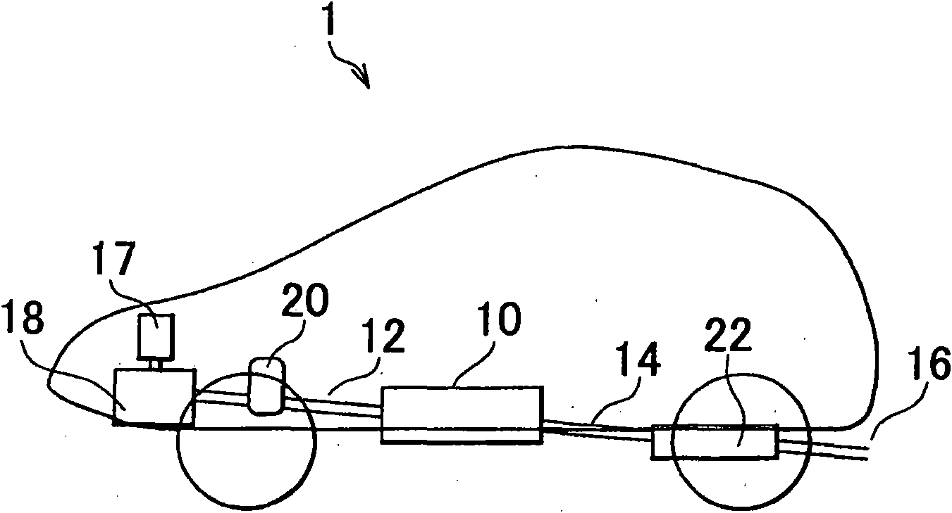
[0044] figure 1 is a diagram showing the structure of the fuel cell automotive vehicle 1 of the first embodiment. Such as figure 1 As shown, a fuel cell motor vehicle 1 is equipped with a fuel cell 10 under the chassis of the vehicle. The fuel cell 10 generates electricity when supplied with air and hydrogen as reaction gases. also, figure 1Only the supply / exhaust system for air is shown, with the hydrogen supply / exhaust system omitted. Air is introduced into a compressor 18 from the front of the vehicle through an air cleaner 17 . Then, the air is pressurized by the compressor 18 and passed through the gas supply passage 12 to be supplied to the fuel cell 10 . The gas supply passage 12 is provided with a humidifier 20 that humidifies the air supplied to the fuel cell 10, thereby adjusting the humidity in the fuel cell. The air passes through the exhaust gas passage 14 after being used for power generation in the fuel cell to be discharged from a gas discharge port 16 pr...


PUM


Abstract

In a motor vehicle equipped with a fuel cell (10), inflow of liquid from outside into the fuel cell (10) is restrained. When it is estimated that there is a risk of liquid flowing into the fuel cell (10) from the gas discharge opening (16) via a gas channel, the exhaust pressure of gas discharged from the gas channel is heightened, or passage through the gas channel is shut.

Description

technical field [0001] The present invention relates to a motor vehicle in which a fuel cell is installed and a control method for the motor vehicle. Background technique [0002] In the case of a motor vehicle in which a fuel cell is installed, it is conceivable that liquid such as water or the like flows in from the outside through an exhaust port or the like due to heavy rain, road flooding, or the like. For example, if water flows in, it degrades the performance of the constituent elements of the fuel cell, or causes a problem in the supply of reaction gas. Japanese Patent Application Laid-Open No. 2004-319167 (JP-A-2004-319167) discloses preventing water from flowing into a fuel cell system by disposing an exhaust port at a position higher than an expected water surface. [0003] However, in the structure in which the air outlet is provided at a high position, the effect of suppressing the inflow of water is lost when the water level or rainfall exceeds an expected ran...

Claims


Application Information

Patent Timeline
Patent Type & Authority Applications(China)
IPC IPC(8): H01M8/04H01M8/00B60L11/18B60F3/00
CPCB60L3/00Y02T90/34Y02T90/32H01M2250/20B60L11/1894H01M8/04402H01M8/04089Y02E60/50H01M8/04753B60L11/1881H01M8/04828B60L58/30B60L58/34Y02T90/40
Inventor 长泽润治
Owner TOYOTA JIDOSHA KK
Why Eureka
Try Eureka