Wireless energy transfer

A technology of wireless energy transmission and energy transmission, which is used in antennas, resonant antennas, loop antennas, etc.

Active Publication Date:
View PDF1 Cites 164 Cited by
  • Summary
  • Abstract
  • Description
  • Claims
  • Application Information

AI Technical Summary

Problems solved by technology

Even for long distances (transmission distance L TRANS >>L DEV , where L DEV is the characteristic size of the device and / or source), directional radiation patterns using lasers or highly directional antennas can also be used effectively for energy transfer, but for moving objects this directional radiation pattern requires an unobstructed line of sight and complex tracking system
Some transmission schemes rely on sensing, but these are generally limited to very close range (L TRANS DEV ) or small power (~mV) energy transfer

Method used


Image

  • Wireless energy transfer
  • Wireless energy transfer
  • Wireless energy transfer

Examples


Embodiment Construction

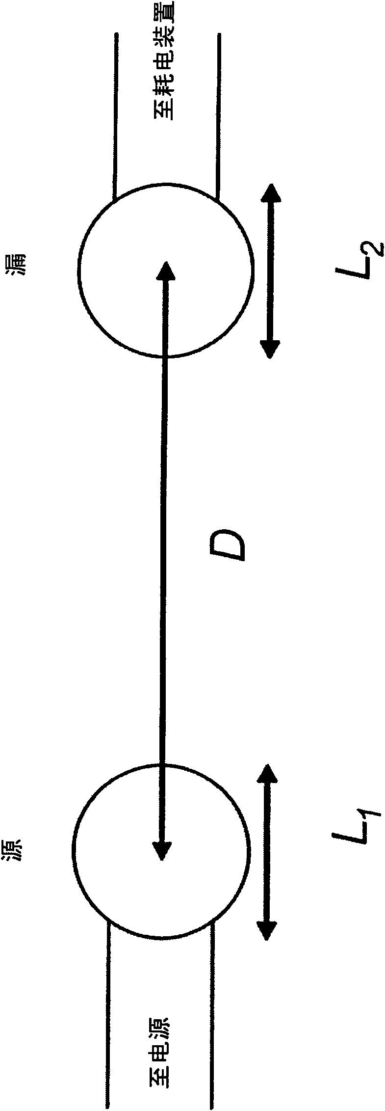
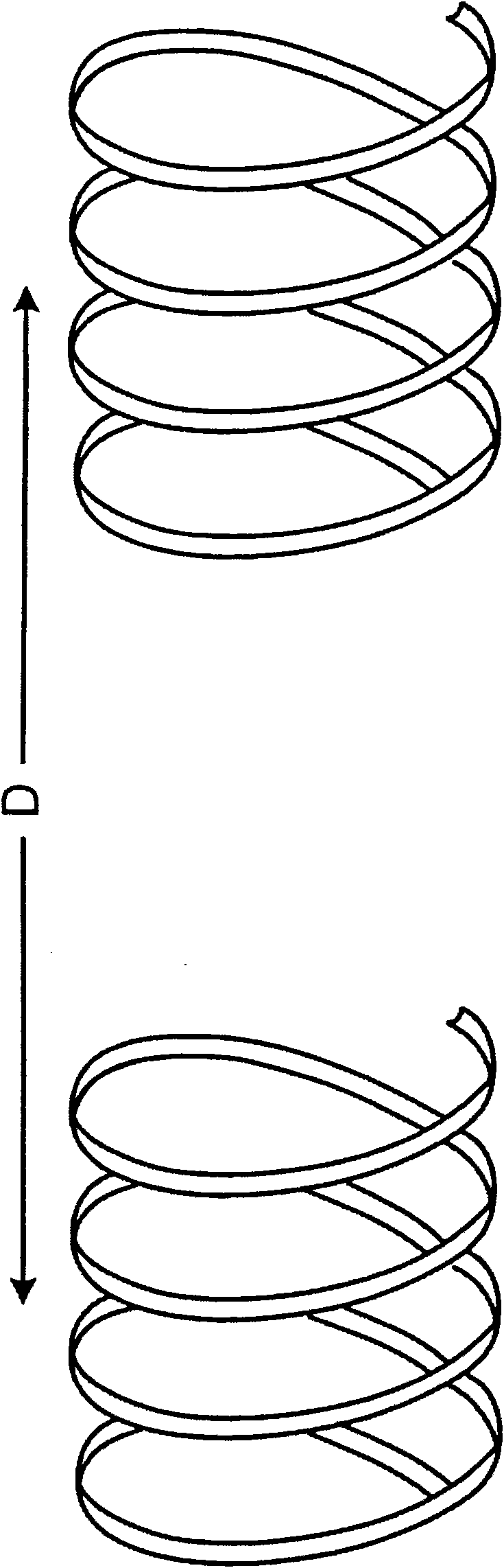
[0078] figure 1 A schematic diagram is shown generally describing an embodiment of the invention in which energy is wirelessly transferred between two resonant objects.

[0079] refer to figure 1 , passing distance D at a characteristic dimension L 1 A resonant source object with a characteristic dimension L 2 The resonant device transfers energy between objects. Both objects are resonant objects. The source object is connected to a power source (not shown) and the device object is connected to a power consuming device (eg a load resistor, not shown). Energy is provided to the source object by the power supply, and the energy is transmitted from the source object to the device object in a wireless and non-radiative manner, and is consumed by the power consumption device. Wireless non-radiative energy transfer utilizing the fields (such as electromagnetic or acoustic fields) of a system of two resonant objects. For simplicity, in the following we will assume that the fiel...


PUM


Abstract

Disclosed is an apparatus for use in wireless energy transfer, which includes a first resonator structure configured to transfer energy non-radiatively with a second resonator structure over a distance greater than a characteristic size of the second resonator structure. The non-radiative energy transfer is mediated by a coupling of a resonant field evanescent tail of the first resonator structure and a resonant field evanescent tail of the second resonator structure.

Description

[0001] Cross References to Related Applications [0002] This provisional application is related to U.S. Patent Application 60 / 908,383, filed March 27, 2007, U.S. Patent Application 11 / 481,077, filed July 7, 2006, and U.S. Provisional Patent Application 60 / 698,442, filed July 12, 2005 . Each of US Patent Application 11 / 481077, filed July 7, 2006, and US Provisional Patent Application 60 / 698,442, filed July 12, 2005 are hereby incorporated by reference in their entirety. Background technique [0003] This application relates to wireless energy transfer. Wireless energy transfer may be used in applications such as powering stand-alone electrical or electronic devices. [0004] The radiation pattern of omnidirectional antennas (which work well for information transmission) is not suitable for this kind of energy transfer, because most of the energy is wasted in free space. Even for long distances (transmission distance L TRANS >>L DEV , where L DEV is the characterist...

Claims


Application Information

Patent Timeline
Patent Type & Authority Applications(China)
IPC IPC(8): H02J17/00
CPCH01Q9/04B60L11/182G06K19/0726H01Q9/30Y02T90/14H02J17/00H01Q7/00Y02T10/7088Y02T90/122Y02T10/7005B60L53/12H02J50/12H02J50/20H02J50/90H02J50/40Y02T10/70Y02T10/7072
Inventor A·卡拉里斯A·B·库尔斯R·莫法特J·D·琼诺普洛斯P·H·费希尔M·索亚契奇
Why Eureka
Try Eureka