Laminated iron core, and its manufacturing method

一种叠层铁芯、制造方法的技术,应用在制造定子/转子本体、磁路形状/式样/结构、电气元件等方向,能够解决性能降低、整形加工的深度有限、扇形铁芯片80卷绕作业性变差等问题,达到制作容易、不容易磨耗的效果

Inactive Publication Date: 2010-03-24
MITSUI HIGH TEC INC
View PDF3 Cites 8 Cited by
  • Summary
  • Abstract
  • Description
  • Claims
  • Application Information

AI Technical Summary

Problems solved by technology

Therefore, there is a problem that the adjacent segment core pieces 80 cannot be aligned without gaps, and the resulting gaps lead to a decrease in the dimensional accuracy of the laminated core and deteriorate the winding workability of the plurality of segment core pieces 80.
In addition, when the broken part protrudes outward from the outer circle of the laminated iron core, a new process for removing it must be provided.
In addition, the depth of the shaping process is limited, and it is not suitable to use this method when a material with a large increase in thickness of the connecting portion 81 is used.
[0016] In addition, if Image 6 As shown in (B), when the portion where the thickness of the bent connecting portion 86 is increased is crushed, the material stretches in the circumferential direction of the connecting portion 86, and gaps are generated between adjacent fan-shaped core pieces 85, and there is a winding. The problem that the pitch size of the fan-shaped core pieces 85 is not uniform and the dimensional accuracy of the laminated core is lowered
[0017] In addition, if Figure 7 As shown in (A), a through hole (releasing hole) 92 is formed in the sector-shaped core sheet 90 of the upper and lower adjacent layers, and the bulging part of the connection part 91 is fitted into the through hole 92, or as shown in FIG. Figure 7 As shown in (B), a notch 97 is formed on the fan-shaped core sheet 95 of the upper and lower adjacent layers, and the bulging part of the connection part 96 fits into the notch 97. In this case, according to the motor using the laminated iron core species, the performance of which may degrade

Method used


Image

  • Laminated iron core, and its manufacturing method
  • Laminated iron core, and its manufacturing method
  • Laminated iron core, and its manufacturing method

Examples


Embodiment Construction

[0057] Hereinafter, embodiments embodying the present invention will be described with reference to the drawings for understanding the present invention.

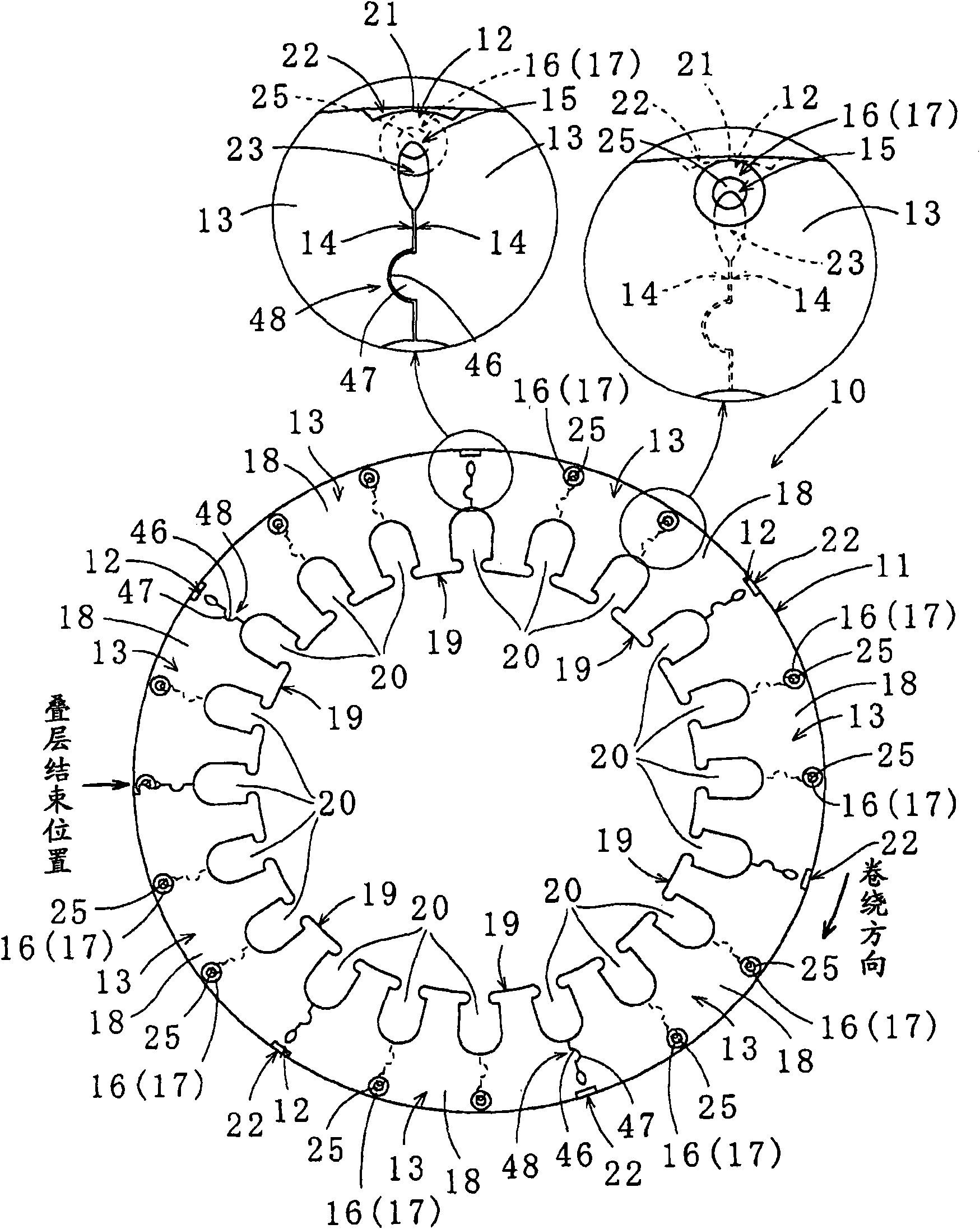
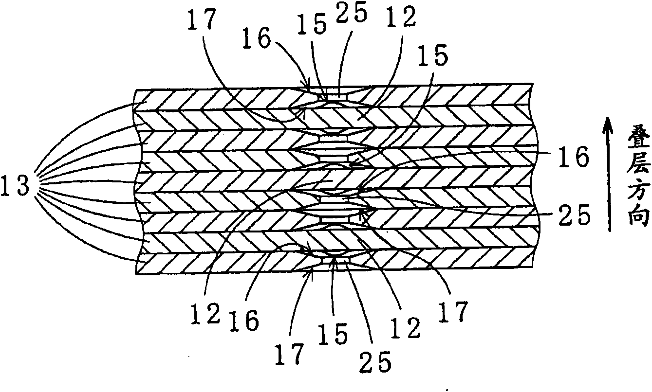
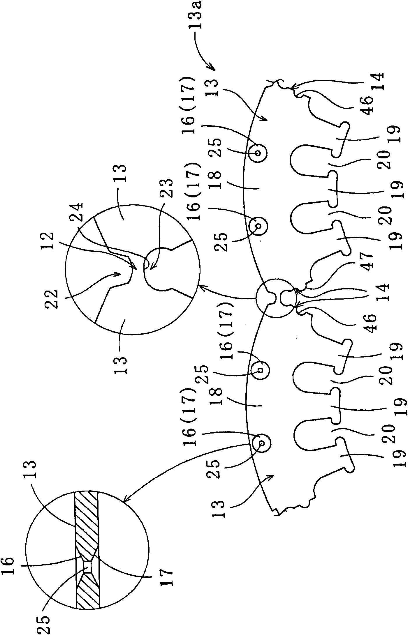
[0058] Such as Figure 1 ~ Figure 3 As shown, in the laminated iron core 10 of the first embodiment of the present invention, each connecting portion 12 is bent, and strip-shaped core pieces 13a are wound and stacked in a spiral shape. The strip-shaped core pieces 13a are connected by connecting portions 12 The fan-shaped iron sheet 13 is formed. In addition, when stacking the sector core pieces 13 , it is preferable to stack them while aligning the radially inner side (the cut groove 20 ) or the outer side of the sector core pieces 13 . In this case, a small gap may also be provided at the side end portions 14 of the adjacent sector-shaped core pieces 13 . In addition, when winding the band-shaped core pieces 13a, the sector-shaped core pieces 13 may be wound and stacked while making the side end portions 14 of the adjac...


PUM


Abstract

The invention provides a laminated core 10 including a plurality of segment core sheets 13 spirally wound and laminated in layers while connecting portions 12 connecting the adjacent segment core sheets 13 are bent, ends of the segment core sheets 13 are aligned with each other and the connecting portions 12 in the adjacent layers are circumferentially displaced relative to each other, the connecting portions 12 located in outer peripheral areas 11 of the segment core sheets 13, the laminated core 10 comprising: a concave cutout 22 formed on a radially outward side of the connecting portion 12, the concave cutout 22 accommodating a radially expanded part 21 within an outer circle of the laminated core 10, the radially expanded part 21 formed in the connecting portion 12 radially outward atthe bending of the connecting portion 12; an interior cutout 23 formed on a radially inward side of the connecting portion 12, the interior cutout 23 defining a bent position of the connecting portion 12; and depressed receptacles 16, 17 respectively formed on a top side and a bottom side of a radially outward area of the segment core sheet 13 except for the connecting portions 12, the depressedreceptacles 16, 17 each receiving a thickness-direction expanded part 15 formed in the connecting portion 12 in a thickness direction thereof at the bending of the connecting portion 12.

Description

technical field [0001] The present invention relates to a laminated iron core formed by winding and stacking a plurality of fan-shaped core pieces connected by connecting parts in a spiral shape and a manufacturing method thereof. The laminated iron core mentioned here refers to the stator and rotor of motors and generators. Background technique [0002] In the past, as a method of improving the yield rate of the core material used in the manufacture of laminated iron cores, when punching the core sheet from the core material, instead of punching the ring-shaped core sheet from the strip-shaped magnetic iron plate, It is to die-cut several fan-shaped core pieces connected into a strip, and then stack the strip-shaped fan-shaped core pieces while winding them to form a laminated core, which is a so-called wound core. [0003] Specifically, for example, as described in Patent Documents 1 to 3, arc-shaped sector-shaped iron core pieces having a predetermined number of slits ar...

Claims


Application Information

Patent Timeline
Patent Type & Authority Applications(China)
IPC IPC(8): H02K1/18H02K15/02
CPCH02K1/148H02K15/02Y10T29/49009
Inventor 明神岩
Owner MITSUI HIGH TEC INC
Why Eureka
Try Eureka