Motor control circuit, motor system, and motor control method

A motor control and circuit technology, applied in the direction of control system, motor generator control, electrical components, etc.

Inactive Publication Date: 2010-03-24
ASAHI KASEI ELECTRONICS CO LTD
View PDF2 Cites 28 Cited by
  • Summary
  • Abstract
  • Description
  • Claims
  • Application Information

AI Technical Summary

Problems solved by technology

However, since the braking force depends on the counter electromotive force voltage, the braking f...

Method used


Image

  • Motor control circuit, motor system, and motor control method
  • Motor control circuit, motor system, and motor control method
  • Motor control circuit, motor system, and motor control method

Examples


Embodiment Construction

[0051] Hereinafter, embodiments of the present invention will be described with reference to the drawings. In addition, in each figure referred in the following description, the same code|symbol is used for the same part as another figure.

[0052] (Structure of motor control circuit)

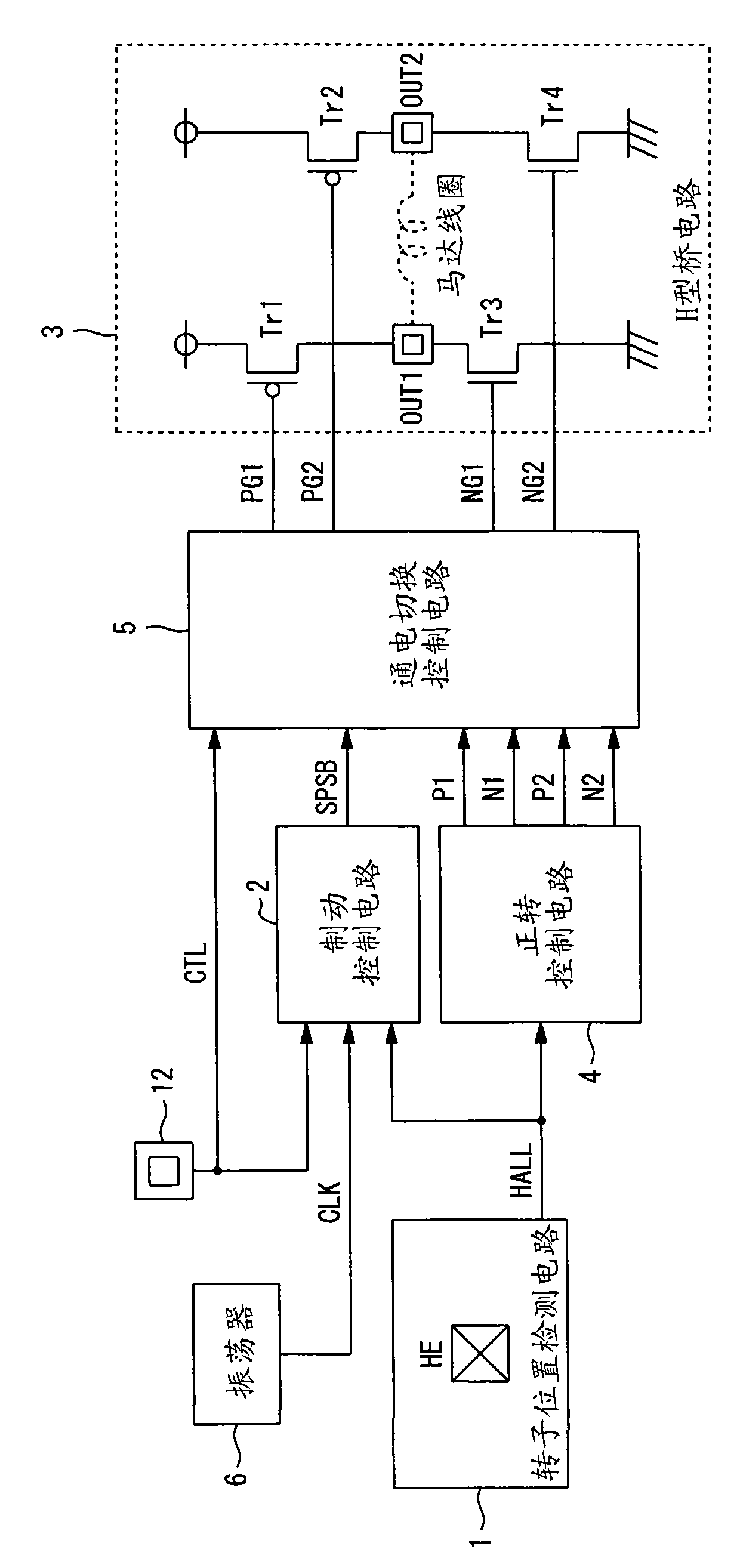
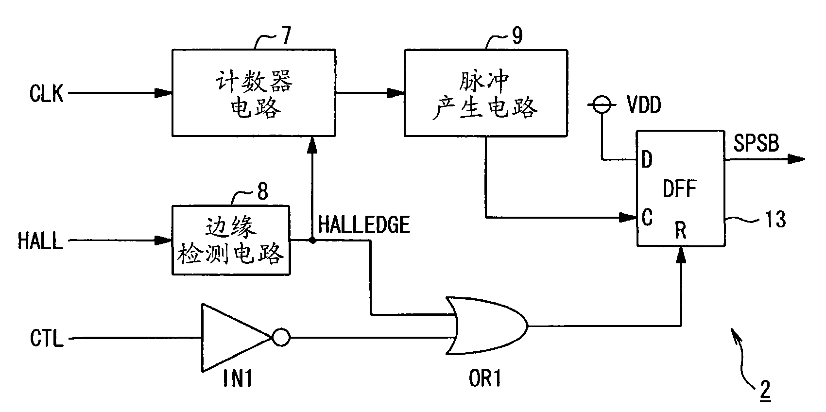
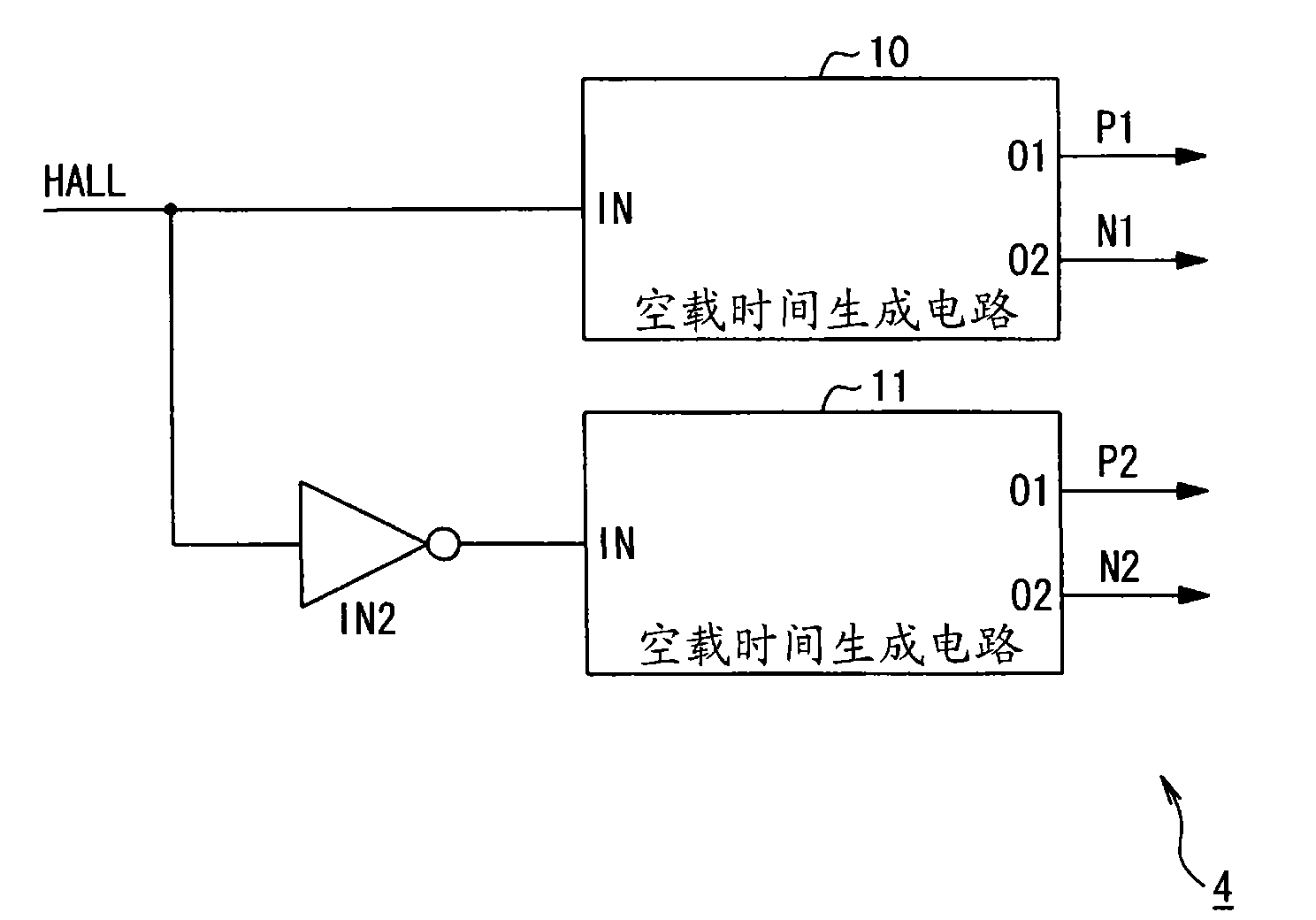
[0053] figure 1 It is a block diagram showing a configuration example of a motor control circuit according to an embodiment of the present invention. As shown in the figure, a rotor position detection circuit 1 is provided, which outputs a rotor position detection signal HALL based on a detection magnetic field detected by a magnetic sensor such as a Hall element HE; and a brake control circuit 2, which outputs a rotor position detection signal based on the rotor position detection signal. HALL to monitor the speed of the motor, and output the brake control signal SPSB for controlling short-pulse reverse braking and short-circuit braking; H-type bridge circuit 3, which drives the motor accor...


PUM


Abstract

Provided is a motor control circuit for controlling the energization of a coil on the basis of the detection result of the position of a rotor. The motor control circuit performs controls to make a stop for a short time by suppressing continuous rotations by inertia and to cause no reverse rotation. When an external control signal (CTL) changes from L to H, a steady rotation control changes to a reversing control so that a reversing brake state comes in. The rotating speed of the motor is monitored, and when the rotating speed attenuates to a set rotating speed, a brake control signal (SPSB) changes from L to H so that a short brake state comes in. However, the motor is caused to continue rotations by inertia, and a position detecting signal (HALL) changes, so that the reversing brake control is performed temporarily (for a time period corresponding to a pulse width (TRB)). This short-pulse reversing brake control is interruptedly performed till the motor stops completely. Thus, the stop can be done for a shorter time period than in the case in which the stop is done only by the short brake control after the motor was decelerated to a rotating speed just before the stop.

Description

technical field [0001] The present invention relates to a motor control circuit, a motor system, and a motor control method for controlling a motor by energizing a motor coil. Background technique [0002] As a method of electrically braking the motor being driven, there are the following control methods: reverse braking control, which conducts electrical braking by applying current to the coil of the motor in the opposite direction to that of forward rotation; and short-circuit braking control , short-circuit the coil ends to perform electrical braking with a current flowing through the back-EMF voltage, which is generated by the magnetic field of the rotor and the coils of the stator (in the case of the inner rotor type , the voltage generated by the magnetic field of the stator and the coils of the rotor). [0003] Figure 11 Changes in the rotational speed when electric braking in the conventional control system is performed are shown. The dotted line S11 indicates the...

Claims


Application Information

Patent Timeline
IPC IPC(8): H02P6/24H02P3/18
CPCH02P3/18H02P6/24
Inventor 福岛贵志
Owner ASAHI KASEI ELECTRONICS CO LTD
Why Eureka
Try Eureka