
Cross-field shrink-fit device and method for limiting magnetic flux losses

A technology of magnetic flux and equipment, used in metal processing equipment, induction heating, manufacturing tools, etc., to achieve high efficiency

Inactive Publication Date: 2012-05-09
FRANZ HAIMER MASCHINENBAU KG
View PDF2 Cites 0 Cited by
  • Summary
  • Abstract
  • Description
  • Claims
  • Application Information

AI Technical Summary

Problems solved by technology

[0009] However, the device described has the disadvantage that although the pole pieces conformally contact the different sleeve segments, this system is far from always ideal

Method used


Image

  • Cross-field shrink-fit device and method for limiting magnetic flux losses
  • Cross-field shrink-fit device and method for limiting magnetic flux losses
  • Cross-field shrink-fit device and method for limiting magnetic flux losses

Examples


Embodiment Construction

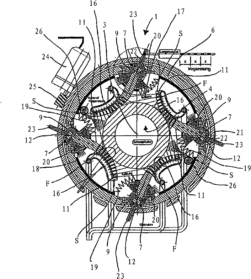
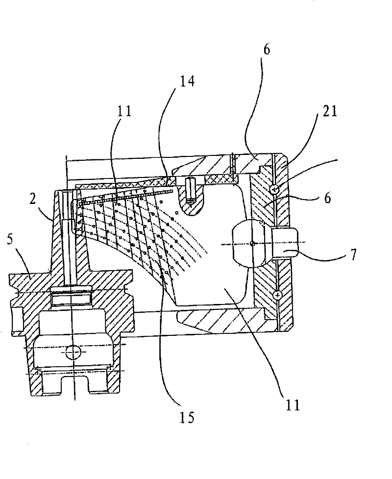
[0045] figure 1 An embodiment illustrating the basic principle of the device according to the invention is shown, here with reference to a chuck device for holding tools. Said device will then be referred to simply as an "induction clip device". The apparatus is provided with or incorporates a controller (not shown) which controls the pole pieces in a particular manner as will be described in detail below so that no substantially short magnetic flux occurs between adjacent pole pieces.

[0046] exist figure 1In , a cross-section of a sleeve section of a holding tool chuck, not shown in detail, is designated by reference number 2 . The sleeve section 2 rotates symmetrically with respect to the working axis of rotation 3 of the clamping tool chuck, in addition to the unbalance caused by tolerances, which cannot be completely avoided but is tolerable, the sleeve section 2 includes the receiver bore 4, the tool The shaft is inserted or can be inserted into the receiver bore 4, ...


PUM


Abstract

The invention relates to a device for inductive heating of an electrically-conducting component section symmetrical relative to an axis, in particular, a sleeve section of a tool clamping chuck for clamping a tool by means of a press fit, wherein the device has several pole pieces made from a magnetically-conducting material arranged in the circumferential direction around the symmetry axis of the component section introduced as required into the device and an induction device for supplying the pole pieces with magnetic flux such that the magnetic flux in pole pieces which are adjacent in thecircumferential direction is opposed. The pole pieces are all mounted on the device such as to be movable about an axis (adjustment rotation axis) running essentially parallel to the axis of symmetryof the component section, such that each of the pole pieces can be adjusted in the direction of the surface region of the individual workpiece by means of a rotation about the provided adjustment rotation axis.

Description

technical field [0001] The invention relates to a device for the induction heating of a component segment, which is axisymmetric and made of electrically conductive material, in particular a sleeve segment associated with a holding tool chuck, provided for Support the receiver opening of the tool with a press fit. Background technique [0002] It is known that components, in particular components rotating symmetrically about an axis, can be heated by induction-generated eddy currents, for example for annealing, tempering or case hardening of components. It is also known that shrinking assemblies of sleeve segments enclosing a wheel axle or mandrel in a press fit, such as a bearing race, can be made to disengage by inductively heating and thereby expanding said sleeve segments mandrel. [0003] Finally, it is also known to retract the cylindrical shaft of a tool to be driven in rotation, such as a drilling machine or a cutting machine, into a cylindrical receiver opening, w...

Claims


Application Information

Patent Timeline
Patent Type & Authority Patents(China)
IPC IPC(8): H05B6/14B23P11/02
CPCB23P11/027H05B6/14Y10T29/49865Y10T29/53
Inventor 弗朗茨・海默尔
Owner FRANZ HAIMER MASCHINENBAU KG
Learn More