Improved structure of cable bridge

A technology for cable trays and improved structures, which is applied in the direction of pipeline supports, pipes/pipe joints/fittings, mechanical equipment, etc., which can solve the problems of difficult manufacturing, complicated process, and inconvenient transportation, and achieve light overall weight, improve transportation efficiency, Ease of transport

Inactive Publication Date: 2010-03-31
殷炳发
View PDF0 Cites 11 Cited by
  • Summary
  • Abstract
  • Description
  • Claims
  • Application Information

AI Technical Summary

Problems solved by technology

[0002] At present, the cable bridges on the market generally use steel to bend the bottom plate and side plates into one piece. This kind of iron bridge has a high overall weight and is inconvenient to carry. For this reason, some operators have developed plastic bridges that are integrally extruded with engineering plastics. However, this Although this kind of bridge frame is light in weight, the process is complex, the manufacture is difficult, the cost is high, and because of its large volume, it also has the disadvantage of inconvenient transportation

Method used


Image

  • Improved structure of cable bridge
  • Improved structure of cable bridge
  • Improved structure of cable bridge

Examples


Embodiment

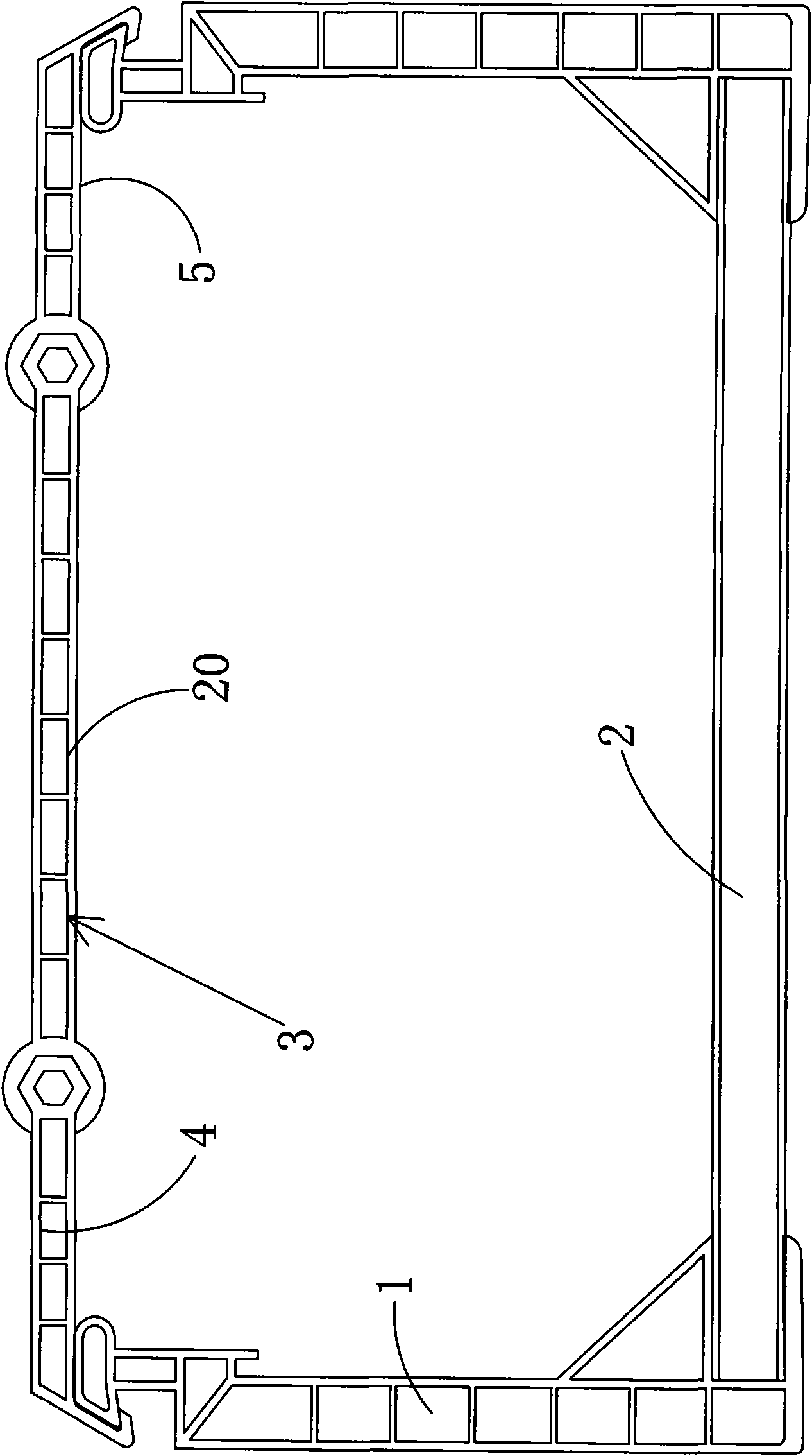
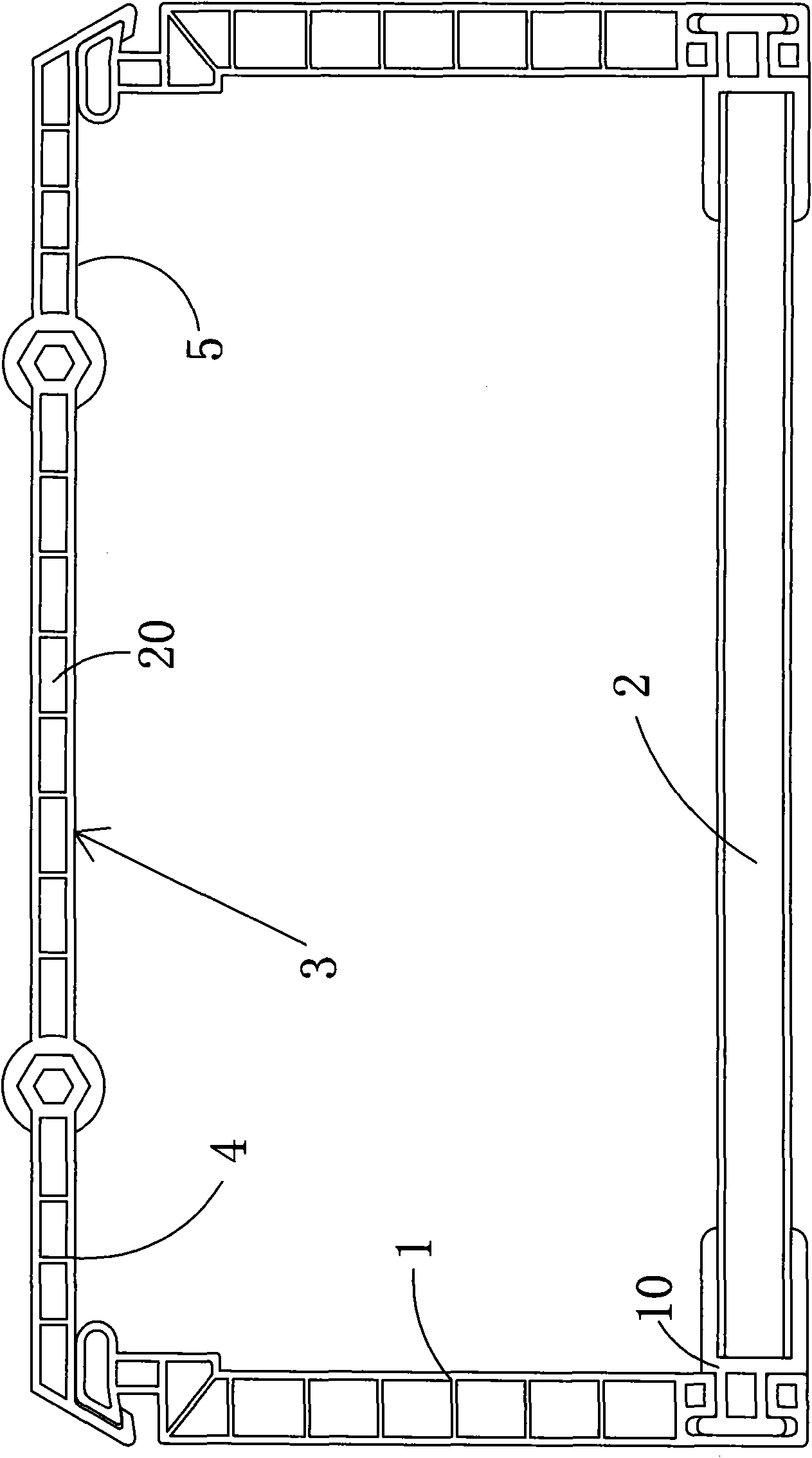
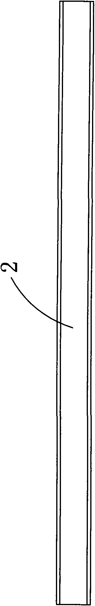
[0023] Embodiment: An improved structure of a cable bridge, including two side plates 1, a bottom plate 2 and a cover plate 3, the bottom plate 2 and the two side plates 1 are formed separately, and the two sides of the bottom plate 2 are respectively detachably fixed to the The bottom of the two side plates 1; the cover plate 3 includes first and second engaging plates 4, 5, wherein one side of the first engaging plate 4 is a convex portion 6, and one side of the second engaging plate 5 is a neck with an opening. The concave notch 7, the convex part 6 can be fixedly engaged in the concave notch 7, the other side of the first and second engaging plates 4, 5 forms a hook groove 8 toward the center of the cable tray, The top of the two side plates 1 is respectively provided with a groove 9 on the side away from the center of the cable tray, the hook groove 8 is fixedly engaged in the groove 9, and the bottom plate 2, the two side plates 1 and the cover plate 3 are all For engine...


PUM


Abstract

The invention discloses an improved structure of a cable bridge, comprising two side plates, a bottom plate and a cover plate, wherein the bottom plate and the two side plates are separated; both sides of the bottom plate can be respectively fixed on the bottoms of the two side plates in a detachable mode; the cover plate comprises a first clamping plate and a second clamping plate, wherein one side of the first clamping plate is a convex part and one side of the second clamping plate is a concave gap with an open neck; the convex part can be fixedly clamped in the concave gap; the other sidesof the first clamping plate and the second clamping plate form a trough towards the central direction of the cable bridge; the tops of the two side plates away from the central side of the cable bridge are respectively provided with a groove; and the troughs are fixedly clamped in the grooves. The bottom plate, the two side plates and the cover plate are plastic engineering products which are individually formed, thereby having low making cost, low making difficulty, light integral weight, small volume, convenient transport and effective enhancement of transport efficiency.

Description

technical field [0001] The invention relates to a cable erecting device, in particular to a structural improvement of a cable bridge. Background technique [0002] At present, the cable bridges on the market generally use steel to bend the bottom plate and side plates into one piece. This kind of iron bridge has a high overall weight and is inconvenient to carry. For this reason, some operators have developed plastic bridges that are integrally extruded with engineering plastics. However, this Although this kind of bridge frame is light in weight, the process is complicated, the manufacturing difficulty is large, the cost is high, and there is the defect of inconvenient transportation because of its large volume. Contents of the invention [0003] In order to overcome the above-mentioned defects, the present invention provides an improved structure of the cable tray, which can effectively reduce the manufacturing cost and difficulty of the cable tray and facilitate transpo...

Claims


Application Information

Patent Timeline
Patent Type & Authority Applications(China)
IPC IPC(8): F16L3/24
Inventor 殷炳发
Owner 殷炳发
Why Eureka
Try Eureka