Drilling clamp for special cover body

A drilling jig and cover technology, which is applied in the direction of drilling molds for workpieces, manufacturing tools, metal processing machinery parts, etc., can solve problems such as inability to process, high tool requirements, difficult processing, etc., to simplify the design difficulty, The effect of simplifying manufacturing difficulty

Inactive Publication Date: 2021-02-02
蒋元明
View PDF0 Cites 4 Cited by
  • Summary
  • Abstract
  • Description
  • Claims
  • Application Information

AI Technical Summary

Problems solved by technology

However, this type of cavity fixture has the problem that the internal cavity is extremely difficult to process, the requirements for the tool are too high, and even the problem that it cannot be processed at all in the closed angle state

Method used


Image

  • Drilling clamp for special cover body
  • Drilling clamp for special cover body
  • Drilling clamp for special cover body

Examples


Embodiment 1

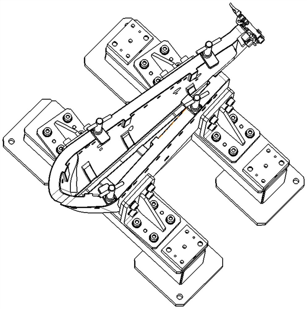
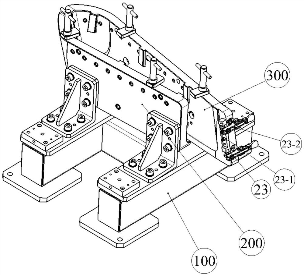
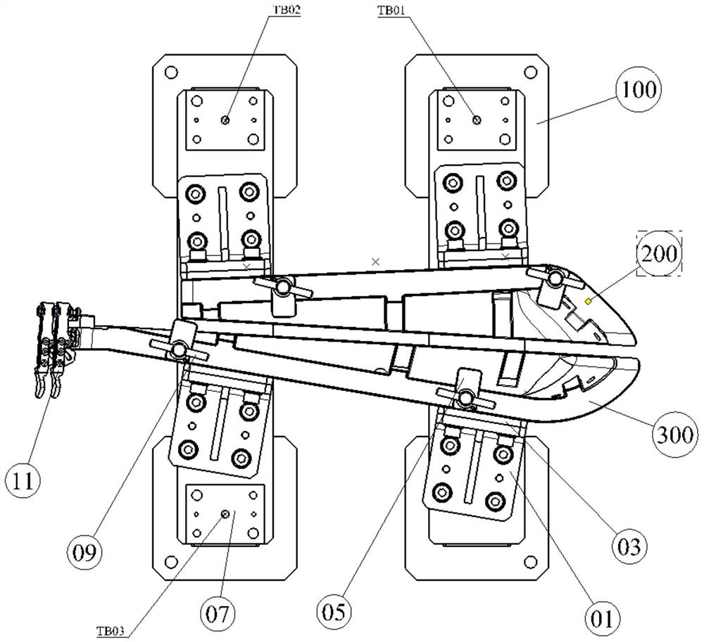
[0022] see Figure 1~9, a drilling jig with a special cover body, consisting of the first jig assembly 200, the second jig assembly 300, the mounting base 100, the connecting angle steel 01, the adjusting gasket 03, the three measuring standard seats 07, the clip The first drilling template assembly 200 consists of a left "half boat"-shaped drilling template 201, a first origin bushing 203, N first drill bushings 205, a A steel wire screw sleeve 207 and clamping pin steel wire screw sleeve 211 are formed. The outer surface of the left "half boat" shaped drilling template is provided with a datum plane A, which is perpendicular to the datum plane A on the left "half boat" shaped drilling template. There are three origin bushing bottom holes processed on the top, and the first origin bushing is installed on the origin bushing bottom hole with an interference fit. The coordinate system constructed with the datum plane A and the origin bushing bottom hole, the left "half" The inn...

Embodiment 2

[0026] The left "half boat" shaped drilling template and the right "half boat" shaped drilling template can also be movably installed on the mounting base in the form of slide rails. After the final theoretical correct positions of the left "half boat" shaped drill template and the right "half boat" shaped drill template are determined by the laser tracker, the left "half boat" shaped drill template and the right "half boat" shaped drill template are Positioning pins are set between the "boat"-shaped drilling templates for plug-in fixation. When the left "half-boat"-shaped drilling template and the right "half-boat"-shaped drilling template are slidable, the problem that the opening and closing angle of some special covers cannot be put into the drilling jig is solved, which is convenient for clamping Work.


PUM


Abstract

The invention relates to a drilling clamp for a special cover body. The drilling clamp is composed of a first drilling jig assembly, a second drilling jig assembly, an installation bottom frame, connecting angle steel, an adjusting gasket, three measurement standard seats, a clamping assembly, a clean margin detection block and an edge clamping device. The first drilling jig assembly is composed of a left half-boat-shaped drill plate, a first origin bushing, N first drill bushings, a first steel wire thread sleeve and a clamping pin steel wire thread sleeve, and the second drilling jig assembly is composed of a right half-boat-shaped drill plate, a second origin bushing, N second drill bushings, a second steel wire thread sleeve and a clamping pin steel wire thread sleeve. The left half-boat-shaped drill plate and the right half-boat-shaped drill plate are fixed to an installation base through the connecting angle steel, and the clamping assembly comprises a pressing plate, a clampingpin and a C-shaped clamp. The drilling clamp for the special cover body is good in machining manufacturability, simple in assembling scheme, low in manufacturing cost and efficient.

Description

technical field [0001] The invention relates to a drilling jig, in particular to a drilling jig with a special cover. Background technique [0002] For cover body parts, such as the shape of the cover body is extremely complex, if the cover body needs to complete the task of hole making, one of the methods is to use numerical control holes. However, due to the extremely complex shape of some covers, it can only be positioned by the shape, and the CNC machine tool cannot use the curved surface shape as the machine tool benchmark to identify, resulting in the hole making work cannot be carried out at all. Another method is to design a special drilling jig to realize the hole making function. For a special type of cover, if the shape of the cover is extremely flat, or even the shape of the cover is double curvature, when the fixture is positioned by the shape, it is necessary to make the fixture into a fixture with an extremely narrow cavity inside. However, this type of cavi...

Claims


Application Information

Patent Timeline
Patent Type & Authority Applications(China)
IPC IPC(8): B23B47/28B23Q17/00
CPCB23B47/28B23B2247/12B23Q17/003
Inventor 蒋元明
Owner 蒋元明
Why Eureka
Try Eureka