Eureka AIR delivers breakthrough ideas for toughest innovation challenges, trusted by R&D personnel around the world.

Shoe-type automatic clutch

An automatic clutch, clutch technology, applied in the direction of automatic clutch, clutch, mechanical equipment, etc., can solve the problems of uneven wear of friction block, shorten the service life of friction block, reduce contact area, etc., to simplify the production process and production difficulty, Reliable power transmission and the effect of increasing the contact area

Inactive Publication Date: 2007-08-15
CHONGQING JIANSHE MOTORCYCLE CO LTD
View PDF0 Cites 4 Cited by
  • Summary
  • Abstract
  • Description
  • Claims
  • Application Information

AI Technical Summary

Problems solved by technology

The disadvantage of this shoe-type automatic clutch is that when the shoe is in a free state, the three shoes cannot form a perfect circle. Only under the action of centrifugal force, the moving point end of the centrifugal arm moves, and the arc on the three shoes However, even in this state, the arc surface of the friction block bonded to the shoe block cannot completely contact the clutch cover, and the contact area is reduced, resulting in a small transmitted torque. , and the wear of the friction block is uneven, shortening the service life of the friction block
At the same time, such a structure also makes it very difficult to accurately locate the outer arc of the shoe when it is welded and formed, which increases the difficulty of production
Moreover, since the return of each centrifugal arm type hoof is controlled by different tension springs, due to the difference in tension springs, the centrifugal or return actions of each centrifugal arm type hoof cannot be unified, affecting the The effect of using the clutch

Method used


Image

  • Shoe-type automatic clutch
  • Shoe-type automatic clutch

Examples


Embodiment Construction

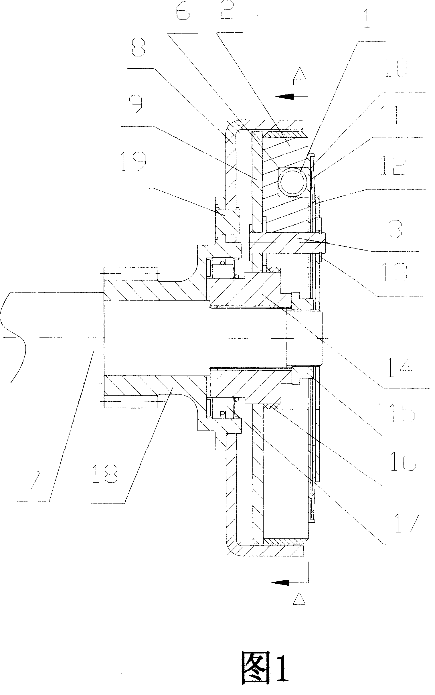
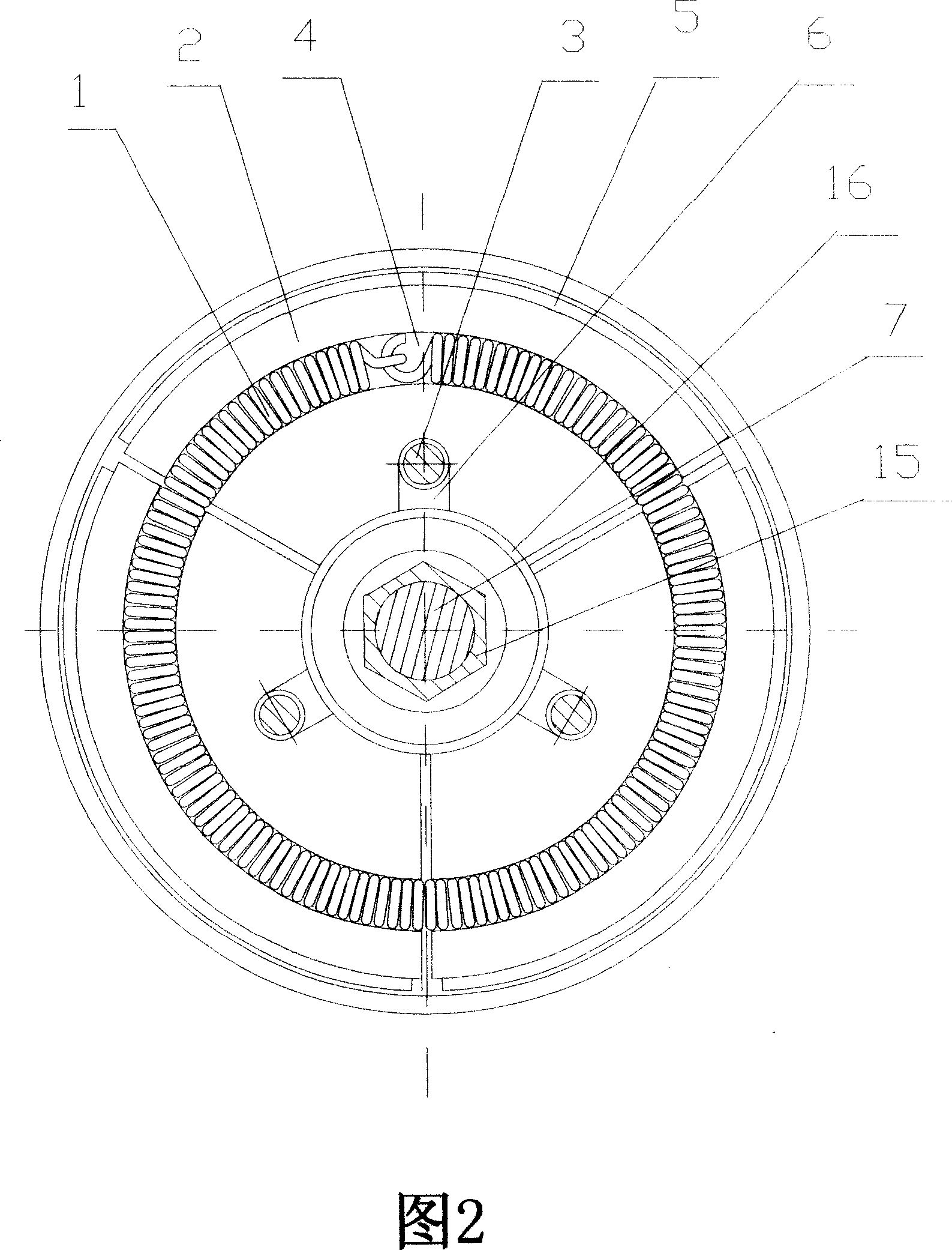
[0011] Referring to FIG. 1 and FIG. 2 , the clutch cover 8 is connected with the driven gear 18 with a shaft hole, and is tightly fixed by a rivet 19 . The shaft hole of the driven gear 18 is a stepped hole, the driving disc 9 is located in the clutch cover 8, and the driving disc 8 is fixedly connected to a shaft sleeve 14 with a spline hole by welding, and the shaft sleeve 14 and the driven gear 18 on the same axis line, the shaft sleeve 14 slides and fits with the inner wall of the large end of the stepped hole of the driven gear 18 through the one-way device 17, and the shaft sleeve 14 with spline holes corresponds to one end of the centrifugal shoe 2. The circumference is covered with rubber Set of 16. Three pin shafts 3 are evenly distributed on the driving disc 9, and the three pin shafts 3 are equally divided into 360°, and are respectively fixed on the driving disc 9 by riveting, or fixed on the driving disc 9 by nut pressing to achieve the same effect. Three centrif...


PUM


Abstract

The invention discloses a mosque automatic clutch, wherein an active cover of the clutch frame is connected with an axial sheath with a spline hole, the active cover is arranged with at least two eccentric mosque blocks which can radial move on the active disc, the inner arc of each eccentric mosque is arranged with a radial sliding groove at middle, the sliding groove of each mosque is sliding engaged with a pin axle of the active disc, the outer arc of each mosque block is adhered with a friction block between which and the inner wall of the clutch frame a clearance space is arranged, each eccentric mosque is arranged with an arc groove while all grooves are connected to form an annular groove, two ends of a flexible spring are connected to be arranged in the annular groove, the annular groove is shaded by a baffle plate, and a baffle ring clamps a pin axle to axially position the eccentric mosque blocks. The invention can contact the arc face of the friction block completely with the clutch frame when in work, to improve torque and make friction uniform to prolong the service life of friction block.

Description

technical field [0001] The invention relates to a shoe-type clutch, in particular to a shoe-type automatic clutch for a motorcycle engine. Background technique [0002] The shoe clutch commonly used in motorcycle engines is generally installed on the crankshaft of the engine. It is characterized by relying on the combination or separation of the shoe and the clutch cover to realize the transmission and interruption of engine power. The existing shoe-type automatic clutch is generally composed of three centrifugal arm-type shoes, and each centrifugal-arm shoe is formed by spot-welding several steel plates with different shapes. The process is complicated and the cost is high. The arc surface of the centrifugal arm type shoe is bonded with a friction block, the fixed point end of each centrifugal arm type shoe block is hinged with the driving disc through a pin shaft, and the moving point end is connected with the fixed point end of another shoe block through a tension spring ...

Claims


Application Information

Patent Timeline
IPC IPC(8): F16D43/18
Inventor 兰华
Owner CHONGQING JIANSHE MOTORCYCLE CO LTD
Why Eureka
Eureka Blog
Learn More