Linear detector packaging structure capable of suppressing stray light and evening light flux and realization method

A packaging structure and detector technology, applied in measuring devices, optical radiation measurement, electric radiation detectors, etc., can solve the problems of difficulty in developing super-large light windows, inconsistent luminous flux, etc., reduce the difficulty of optical processing, simplify the difficulty of preparation, The effect of easy operation

Active Publication Date: 2017-02-01
SHANGHAI INST OF TECHNICAL PHYSICS - CHINESE ACAD OF SCI
View PDF6 Cites 5 Cited by
  • Summary
  • Abstract
  • Description
  • Claims
  • Application Information

AI Technical Summary

Problems solved by technology

[0004] The purpose of the present invention is to provide a linear detector package structure and implementation method for stray light suppression and luminous flux uniformity, and to solve the problem of the middle photosensitive element and both side photosensitive elements in the spliced ​​6000-30000 yuan linear detector chip package The problem of inconsistency of the corresponding luminous flux solves the problem of difficulty in the development of super large light windows of the spliced ​​6000-30000 element line array detector assembly, so that the spliced ​​6000-30000 element line array detector assembly can better achieve stray light suppression and Detector Luminous Flux Homogenization

Method used


Image

  • Linear detector packaging structure capable of suppressing stray light and evening light flux and realization method
  • Linear detector packaging structure capable of suppressing stray light and evening light flux and realization method
  • Linear detector packaging structure capable of suppressing stray light and evening light flux and realization method

Examples


Embodiment Construction

[0071] Below join accompanying drawing to be described in further detail to the embodiment of the present invention in embodiment:

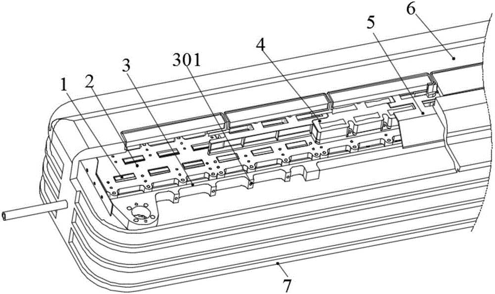
[0072] This embodiment is a package structure of 30000 linear array detectors used for stray light suppression and luminous flux uniformity, as attached figure 1 As shown, its main implementation method is as follows:
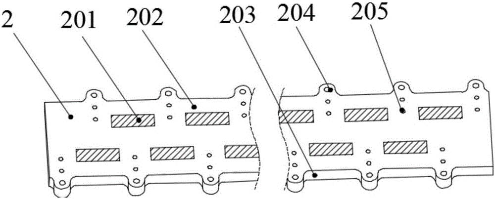
[0073] 1) The spliced ​​linear detector 1 is composed of 30 small-scale infrared detectors spliced ​​in the shape of "pin" and glued and solidified on the detector spliced ​​substrate 2 . The splicing substrate 2 of the detector is a rectangular plate-shaped structure, which is made of Kovar material. During the process of machining and forming, it undergoes 10 times of liquid nitrogen shocks, and the cooling rate is 4°C / s for metallographic pretreatment and stress release. The sub-processing repair makes the flatness and parallelism of the upper and lower surfaces of the spliced ​​substrate 2 of the detector meet the requirement...


PUM


Abstract

The invention discloses a linear detector packaging structure capable of suppressing stray light and evening light flux and a realization method. The linear detector packaging structure capable of suppressing stray light and evening light flux comprises a stitching-type linear detector, a detector stitching substrate, a detector transition substrate, a cold shield assembly stitched by five filters and a tesseral cold shield part, a radiation shield, a light window assembly stitched by five Z-type sub light windows internally provided with six discrete light through holes for each sub light window, and a long linear dewar bottom plate. Through introducing specific processing, the thirty sub modules of the stitching-type linear infrared detector are corresponding to the thirty slender waist-type light through holes of the tesseral cold shield and the discrete thirty light through holes of the super large light window, light physical isolation and light flux evenness of adjacent sub module detectors can be realized, and the performance evenness of the linear detector and the assembly application stray light suppression ability can be effectively improved. The structure is simple, the operation is convenient, and the maintenance performance is good. Due to the large-size light window assembly manufacturing method of the invention, the optical processing difficulty of the light window can be reduced, and the finished product rate is improved.

Description

technical field [0001] The invention relates to an infrared detector packaging technology, in particular to a linear array detector packaging structure and implementation method for stray light suppression and luminous flux uniformity, which is suitable for the packaging of spliced ​​linear array detector chips. It is also suitable for the packaging of multi-module spliced ​​area array detector components for stray light suppression for push-broom wide-field optical systems. Background technique [0002] Two important performance indicators of infrared remote sensing instruments are field of view and resolution. In the development of high-resolution large-field optical systems, in order to overcome the contradiction between field of view and resolution, one of the solutions is to use high-resolution, ultra-large-scale infrared focal plane detectors. Infrared detectors are limited by manufacturing process, fill factor, sensitivity, yield, cost and other factors, and their sc...

Claims


Application Information

Patent Timeline
Patent Type & Authority Applications(China)
IPC IPC(8): G01J5/06G01J5/08G01J5/10G01J5/20
CPCG01J5/06G01J5/08G01J5/0875G01J5/10G01J5/20G01J2005/202Y02P70/50
Inventor 王小坤李俊孙闻曾智江郝振贻陈俊林李雪
Owner SHANGHAI INST OF TECHNICAL PHYSICS - CHINESE ACAD OF SCI
Why Eureka
Try Eureka