
Probe tip

A probe, cutting-edge technology, applied in the field of measurement equipment, can solve problems such as low, cumbersome efficiency

Active Publication Date: 2010-03-31
LAKE SHORE CRYOTRONICS INC +1
View PDF5 Cites 4 Cited by
  • Summary
  • Abstract
  • Description
  • Claims
  • Application Information

AI Technical Summary

Problems solved by technology

This is a tedious and inefficient process, especially when scanning a wide temperature range

Method used


Image

  • Probe tip
  • Probe tip
  • Probe tip

Examples


Embodiment Construction

[0049] [048] While illustrative embodiments of the general inventive concept are shown in the accompanying drawings, it should be understood that this disclosure should be considered an illustration of the general inventive concept as herein described and claimed.

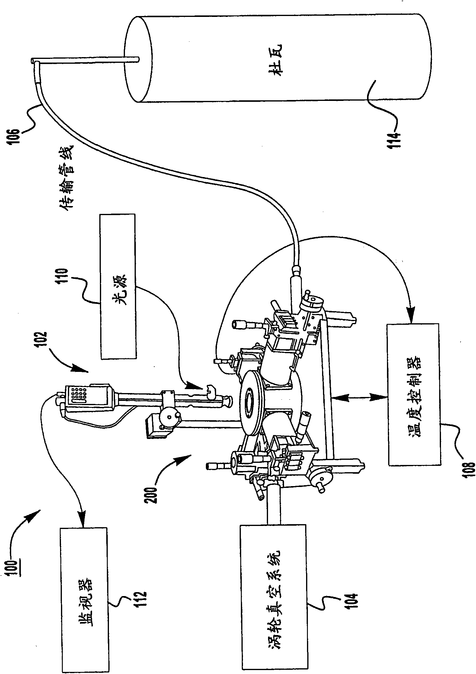
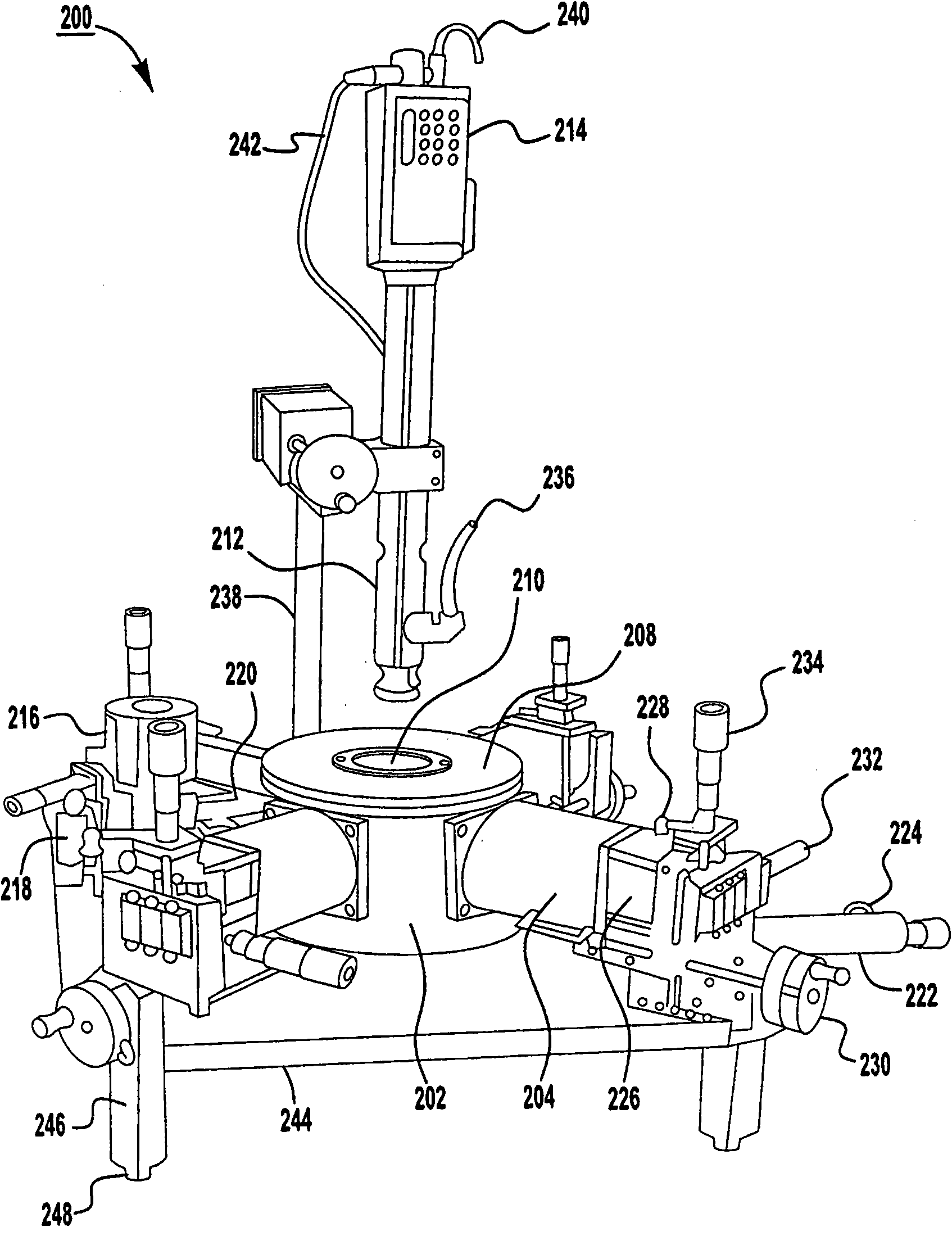
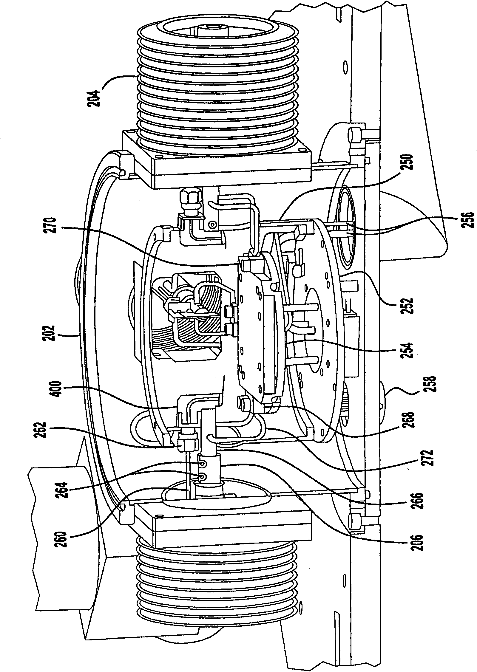
[0050] [049] A probe station according to an exemplary embodiment includes a probe tip that facilitates automatic full-scale or wide-scale temperature range scanning with minimal, if any, displacement of the probe tip. For example, the probe station may be a TTP4 type probe station manufactured and sold by Lake Shore Cryotronics, Inc (hereinafter referred to as "TTP4 probe station"). In general, the operation of the TTP4 Probe Station as an exemplary probe station is described in the TTP4 Probe Station Operating Guide, Version 1.0 (October 25, 2005).

[0051] [050] According to an exemplary embodiment, the TTP4 probe station 200 may be part of the measurement system 100, such as figure 1 shown. Measurement syste...


PUM

PropertyMeasurementUnit
Lengthaaaaaaaaaa
Lengthaaaaaaaaaa

Abstract

To eliminate or otherwise reduce unintended movement of a probe tip of a probe assembly being held by a probe arm, the probe assembly includes one or more resilient members that compensate for the contraction or expansion of the probe arm in accordance with the coefficient of thermal expansion of the material from which the probe arm is made. Thus, the probe tip can remain in contact with a sample being measured at the desired location on the sample, during an automated full or wide scale temperature range sweep.

Description

[0001] related application [0002] [001] This application is filed as a patent application under the Paris Convention and claims priority to US Provisional Patent Application No. 61 / 091,962, filed August 26, 2008. technical field [0003] [002] The present invention relates generally to measurement equipment and, more particularly, to mechanical probe stations. Background technique [0004] [003] Mechanical probe stations can be used to measure properties of semiconductor materials and devices (ie, samples) at cryogenic conditions. For example, a probe station can be used to physically acquire signals from internal nodes of a semiconductor device. A probe station uses a robotic arm that allows precise positioning of fine needles (ie, probe tips) on the surface of a semiconductor device. If the device is electrically excited, the probe station acquires the signal and displays it on the oscilloscope. Probe stations are commonly used for failure analysis of semiconductor d...

Claims


Application Information

Patent Timeline
IPC IPC(8): G01R1/067
CPCG01R31/2863G01R1/06716G01R1/06755
Inventor J·C·考迪尔E·C·马卢夫山口政纪水田慎一朗
Owner LAKE SHORE CRYOTRONICS INC
Learn More