
Power environment monitoring system

A dynamic environment monitoring and monitoring point technology, applied in transmission systems, transmission monitoring/testing/fault measurement systems, digital transmission systems, etc., can solve the problems of system stability and saving circuit resources that cannot be taken into account at the same time.

Inactive Publication Date: 2010-03-31
中国移动通信集团甘肃有限公司
View PDF0 Cites 5 Cited by
  • Summary
  • Abstract
  • Description
  • Claims
  • Application Information

AI Technical Summary

Problems solved by technology

[0009] The purpose of the present invention is to provide a power environment monitoring system to solve the problem that the system stability and circuit resource saving cannot be taken into account at the same time in the existing monitoring system

Method used


Image

  • Power environment monitoring system
  • Power environment monitoring system
  • Power environment monitoring system

Examples


Embodiment Construction

[0023] The specific implementation manners of the present invention will be described in detail below in conjunction with the accompanying drawings.

[0024] In this specific implementation manner, a VC12 time slot, also called a V12 granule, is specifically a PCM 2M link, that is, a 2M link hereinafter.

[0025] The networking method of the power environment monitoring system in the embodiment of the present invention includes:

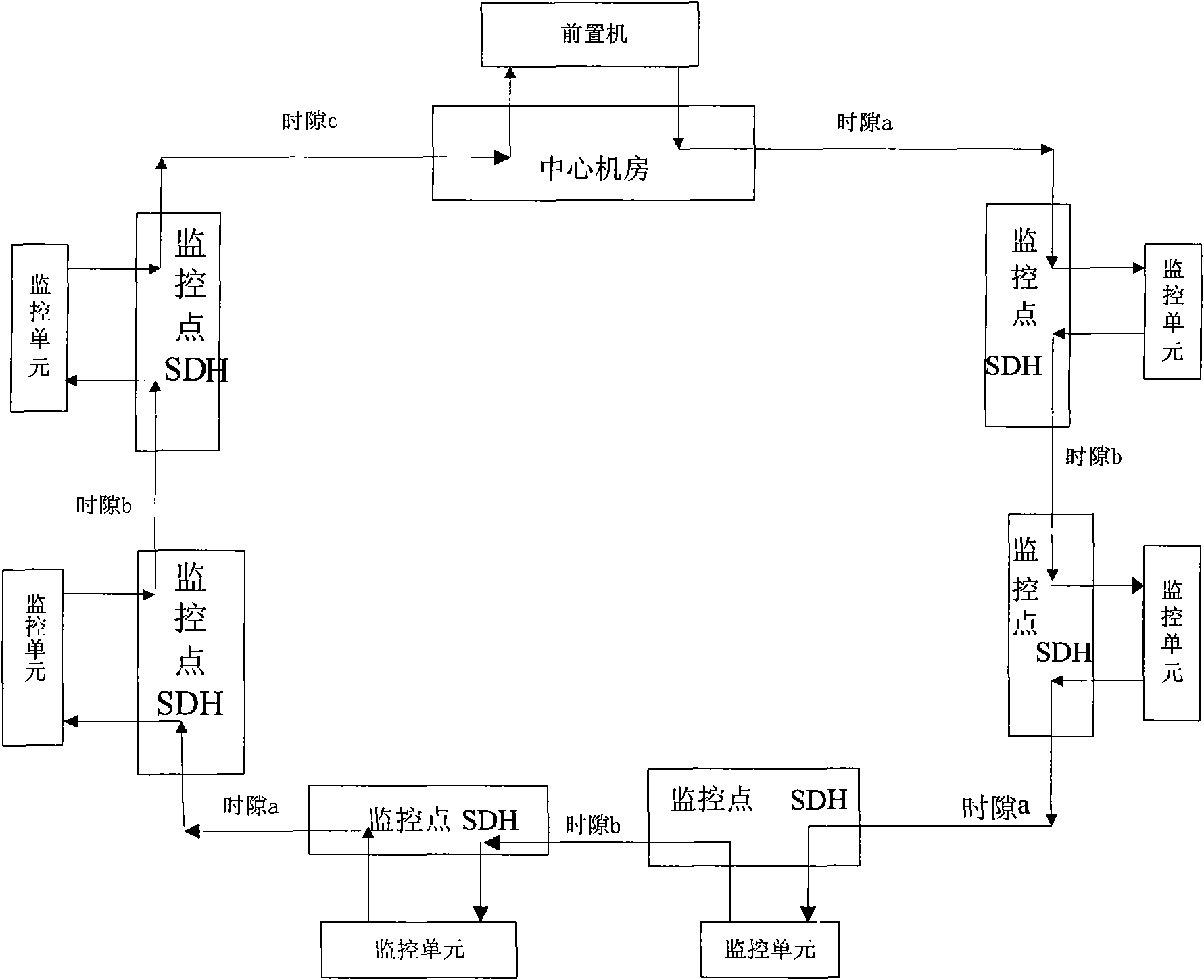
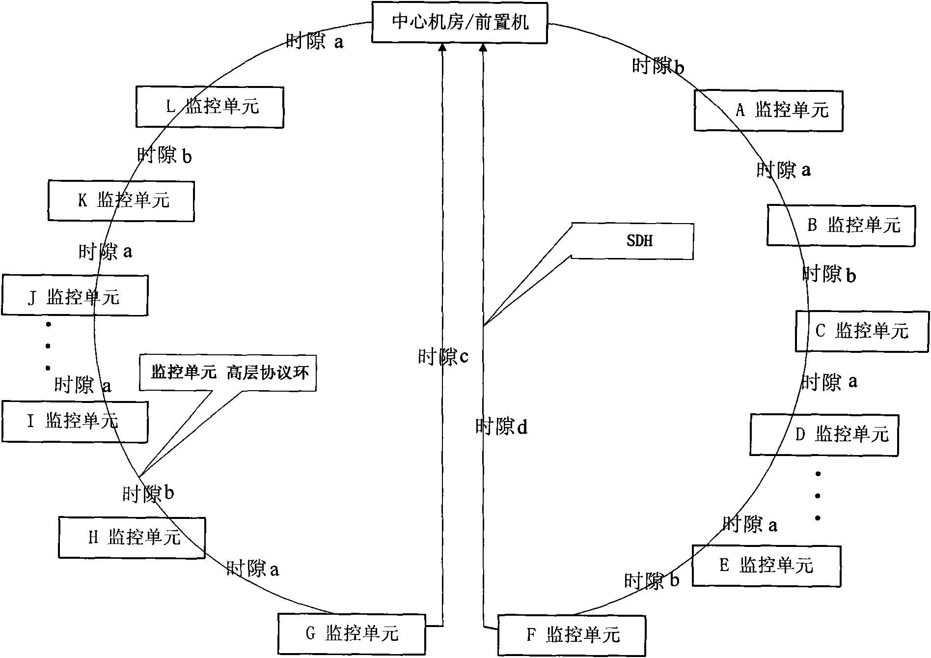
[0026] Step 1, set the ring monitoring network structure, set monitoring points on the base stations that the ring monitoring network structure needs to monitor, and install monitoring units at each monitoring point;

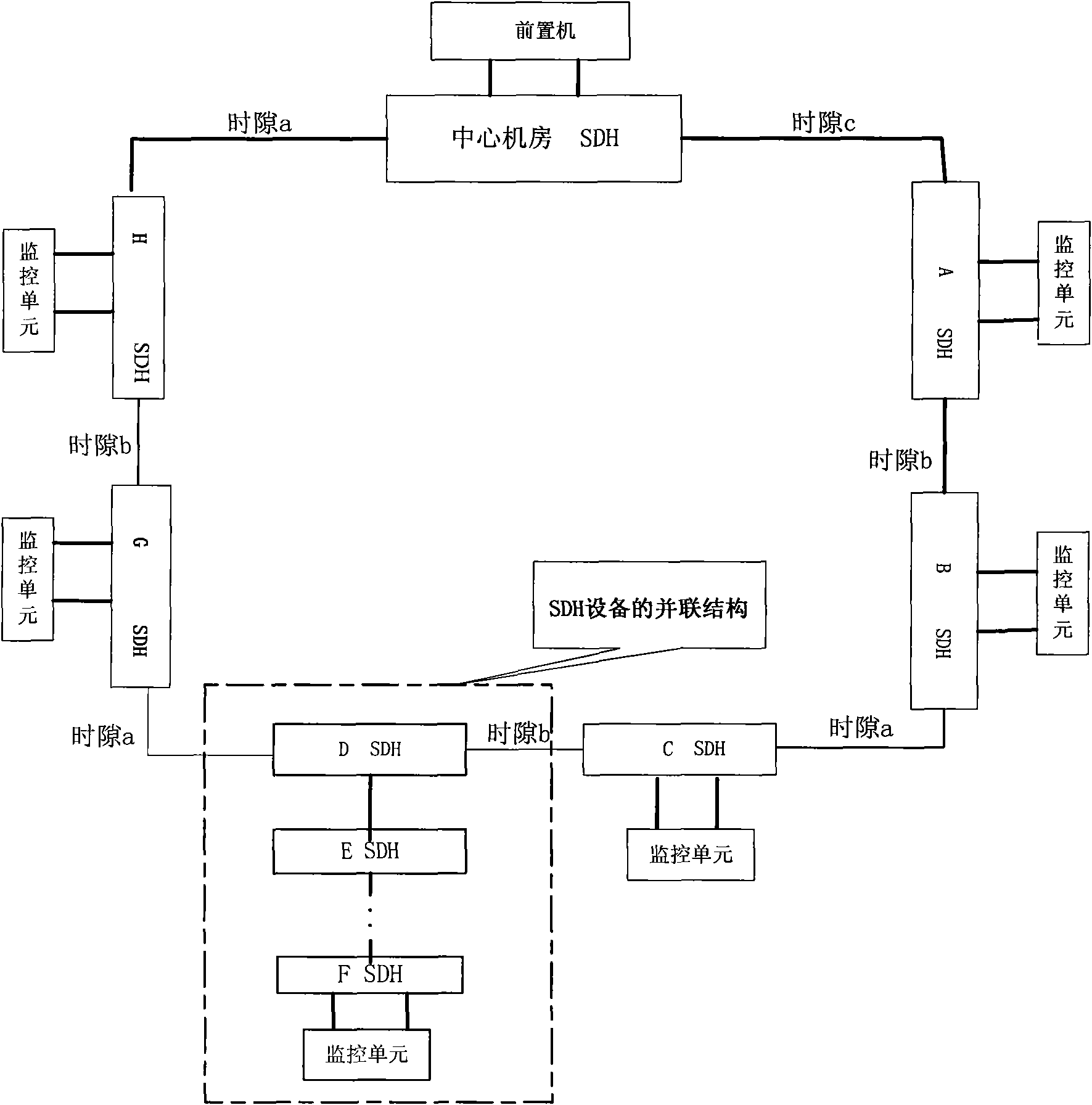
[0027] Step 2, install corresponding SDH (Synchronous Digital Hierarchy, synchronous digital network) equipment at each monitoring point;

[0028] Step 3. Lay out cables for each monitoring point. The two 2M ports on the SDH equipment are respectively connected to the UP port and the DOWN port of the monitoring unit. The two ends of ...


PUM


Abstract

The invention discloses a power environment monitoring system, mainly applied to the mobile communication field. The power environment monitoring system comprises a central machine room SDH device, aplurality of monitoring point SDH devices, front-end processors connected in parallel with the central machine room SDH device, and monitoring units connected in parallel with the monitoring point SDHdevices, wherein the central machine room SDH device and the monitoring point SDH devises devices are connected to form an SDH access in a ring shape or link shape, the SDH circuit is provided with aspecial link for transmitting monitoring data, and each monitoring unit copies the self-obtained monitoring data to a specified time slot of the specific link and then transmits the data to the front-end processors. The power environment monitoring system is designed to save the resource of transmission circuits of the power environment monitoring system in maximum and fully utilizes the characteristic that the monitoring unit extracts the time slot to build safe, reliable and highly efficient network structure of the power environment monitoring system.

Description

technical field [0001] The invention relates to a monitoring system applied in the field of mobile communication, in particular to a power environment monitoring system. Background technique [0002] The transmission circuit of the power environment monitoring system of each mobile operator mainly adopts the following two structures: [0003] 1. The power environment monitoring transmission of the base station provides the power environment monitoring transmission circuit of the base station by sharing a 2M link in front of the BTS equipment of the base station. [0004] Advantages: Save local network transmission circuit resources. [0005] Disadvantages: It occupies a fixed time slot of 2Mb / s circuit system, which has a certain impact on the carrier frequency expansion of the base station, and the system operation is unstable, which has an adverse impact on the base station business. The 2M cable connection in the monitoring center computer room is complicated and requir...

Claims


Application Information

Patent Timeline
IPC IPC(8): H04L12/26H04L9/08H04B10/08H04J3/08H04B10/07
Inventor 梁彦斌吴少雄杨德邵艳林
Owner 中国移动通信集团甘肃有限公司
Learn More