
Heat radiation device

A technology of heat dissipation device and heat dissipation module, applied in cooling/ventilation/heating transformation, electrical components, electric solid devices, etc., can solve problems such as loss of function, affecting the performance of electronic devices, circuit damage, etc.

Inactive Publication Date: 2010-03-31
AMA PRECISION INC
View PDF0 Cites 4 Cited by
  • Summary
  • Abstract
  • Description
  • Claims
  • Application Information

AI Technical Summary

Problems solved by technology

If there is no proper mechanism to dissipate the heat outside the electronic device, the integrated circuit will not be able to withstand the heat, so it will be damaged and affect the performance of the overall electronic device, or even lose its function.
[0003] Traditional cooling devices are mostly fixed in the host, or can only move the cooling device slightly relative to the heating element, but such a distance cannot keep the dissipated heat away from the host, and there is still a great possibility that the host will be damaged. still have an impact
Such a design cannot effectively remove heat energy from the electronic device. If there is no more efficient way to remove heat energy due to the more complex progress of current circuit design, it will be easy to accumulate too much heat energy in the electronic device. The circuit is overheated and damaged in the electronic device

Method used


Image

  • Heat radiation device
  • Heat radiation device
  • Heat radiation device

Examples


Embodiment Construction

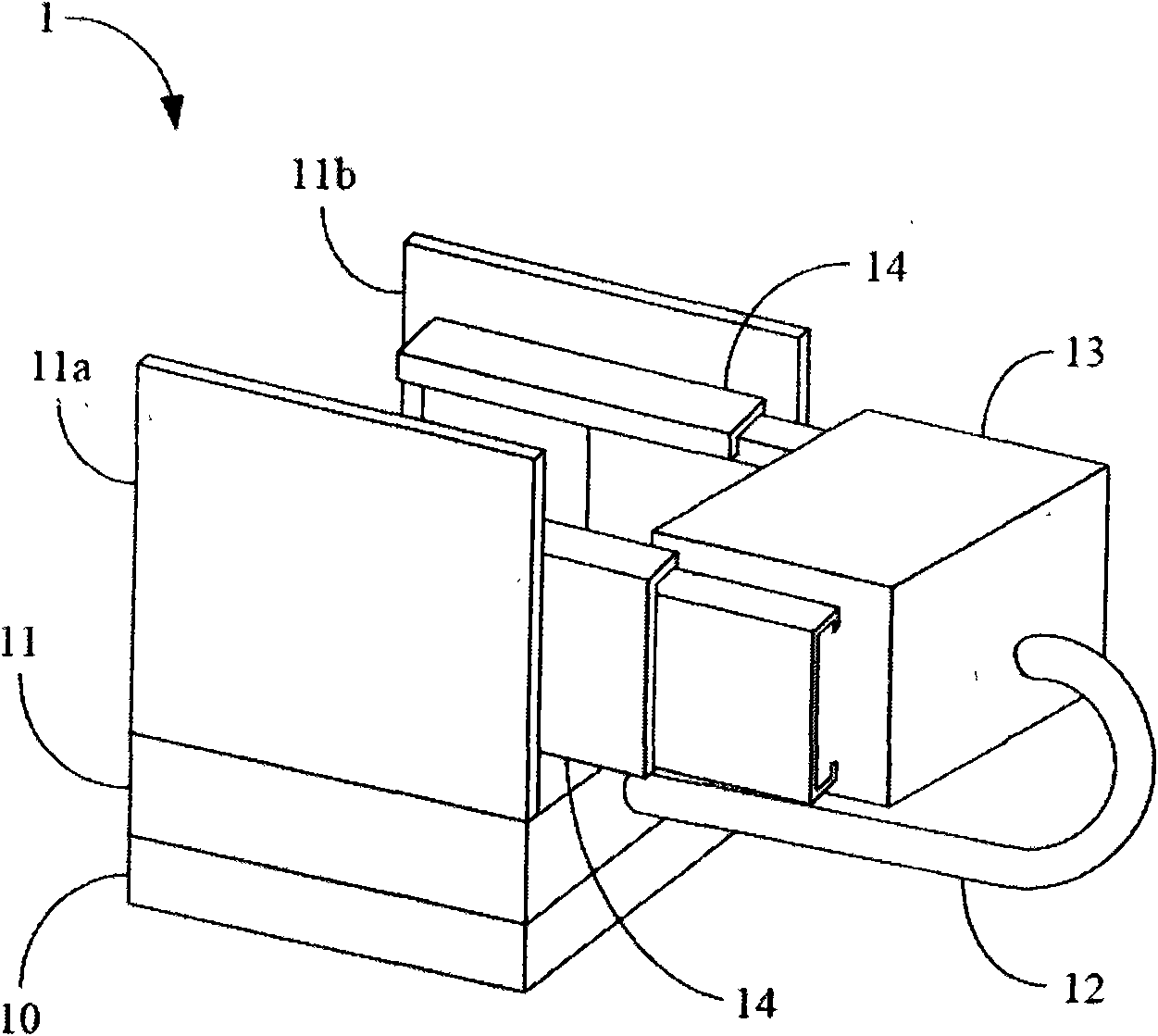
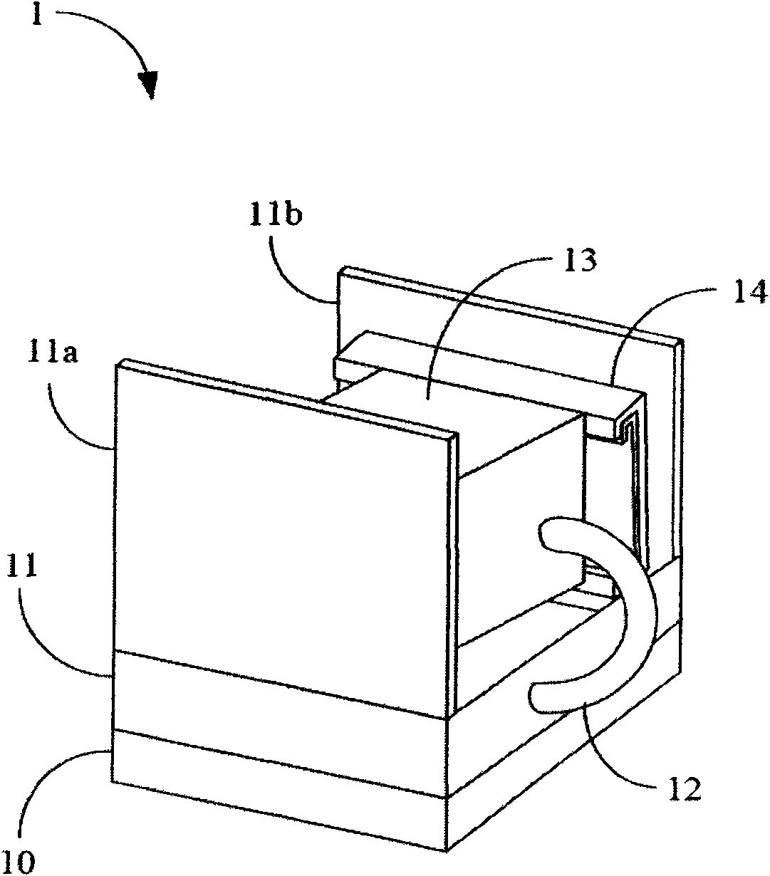
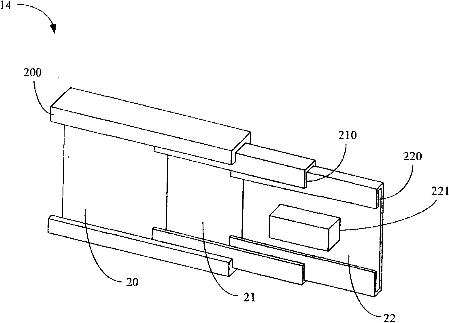
[0017] Please also refer to Figure 1A and Figure 1B , are perspective views of a heat dissipation device 1 according to the first embodiment of the present invention, applied to a heating element 10 , including: a fixed heat dissipation module 11 , a heat pipe 12 , a mobile heat dissipation module 13 and a telescopic connector 14 . The fixed heat dissipation module 11 is arranged on the heating element 10. In this embodiment, the fixed heat dissipation module 11 is substantially as Figure 1A As shown, it is a heat sink, and includes two vertical walls 11a and 11b. In the form of a heat dissipation plate, the fixed heat dissipation module 11 can directly dissipate heat to the heating element 10 . One end of the heat pipe 12 is slidably disposed on the fixed heat dissipation module 11 , that is, a part of the heat dissipation plate, and the other end of the heat pipe 12 is fixed on the mobile heat dissipation module 13 . Both ends of the telescopic connector 14 are also resp...


PUM


Abstract

The invention relates to a heat radiation device which is applied to a heating element and comprises a fixed heat radiation module, a heat pipe, a movable heat radiation module and at least one telescopic connection component. The fixed heat radiation module is arranged at the heating element; one end of the heat pipe is arranged at the fixed heat radiation module in a sliding way, and the other end of the heat pipe is fixed at the movable heat radiation module; and both ends of at least one of the telescopic connection components after extending are respectively connected with the movable heat radiation module and the fixed heat radiation module, the telescopic connection components comprise a plurality of assistant connection components, each assistant connection component comprises a slide rail part used for supporting and connecting the adjacent assistant connection components to lead the two adjacent assistant connection components to slide oppositely.

Description

technical field [0001] The present invention relates to a heat dissipation device, and in particular to a heat dissipation device applied to a heating element. Background technique [0002] Under the increasingly precise and complex design of electronic devices, many new issues to be solved have been extended. Among them, more and more dense integrated circuits will generate a large amount of heat energy, and heat energy will be one of the most serious problems in a small circuit space. If there is no proper mechanism to dissipate the heat outside the electronic device, the integrated circuit will not be able to withstand the heat, and thus suffer from wear and tear, affecting the performance of the entire electronic device, or even losing its function. [0003] Traditional cooling devices are mostly fixed in the host, or can only move the cooling device slightly relative to the heating element, but such a distance cannot keep the dissipated heat away from the host, and the...

Claims


Application Information

Patent Timeline
Patent Type & Authority Applications(China)
IPC IPC(8): H05K7/20H01L23/34H01L23/427
Inventor 张秉钧连颜杨
Owner AMA PRECISION INC
Learn More