An auxiliary equipment for bolt connection in the construction of a steel structure building

A technology of auxiliary equipment and house building, applied in the direction of building structure, construction, and building materials processing, etc., can solve the problems of low work efficiency, labor-intensive, cumbersome operation process, etc., and achieve improved work efficiency, simple manual operation, saving human effect

Active Publication Date: 2022-03-01
佛山市南方新联物流装备制造有限公司
View PDF0 Cites 0 Cited by
  • Summary
  • Abstract
  • Description
  • Claims
  • Application Information

AI Technical Summary

Problems solved by technology

[0006] In order to overcome the shortcomings of the above-mentioned method, such as cumbersome operation process, low work efficiency, and relatively labor-intensive operation, the technical problem to be solved by the present invention is to provide a steel structure that is easy to operate, can improve work efficiency, and saves manpower. Bolting auxiliary equipment for building construction

Method used


Image

  • An auxiliary equipment for bolt connection in the construction of a steel structure building
  • An auxiliary equipment for bolt connection in the construction of a steel structure building
  • An auxiliary equipment for bolt connection in the construction of a steel structure building

Examples


Embodiment 1

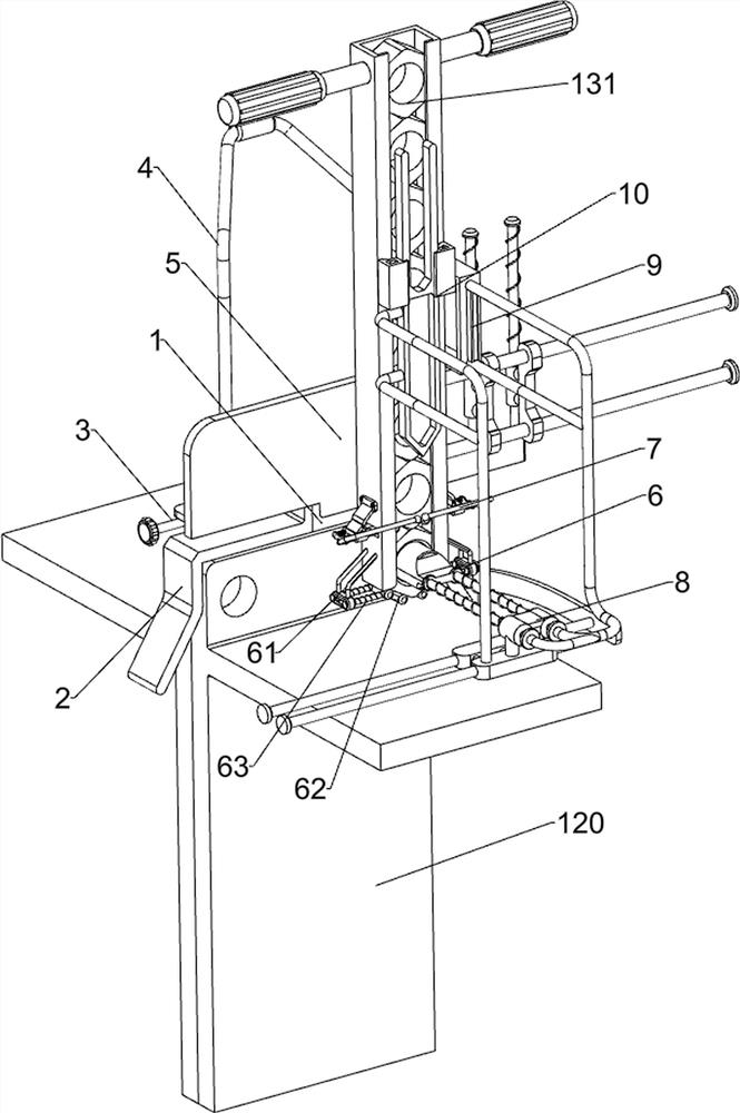
[0027] A kind of bolt connection auxiliary equipment for steel structure building construction, such as Figure 1-4 As shown, it includes a first extruding frame 1, a second extruding frame 2, a screw rod 3 and a first handle 4, and the first extruding frame 1 is slidably connected with a second extruding frame 2, and the first extruding frame 1 The screw rod 3 is connected to the upper rotation, and the screw rod 3 is threadedly matched with the second extrusion frame 2. The first handle 4 is connected to the top of the first extrusion frame 1. It also includes a moving assembly 5, a limit assembly 6 and a material blocking assembly 7. The first extrusion frame 1 is provided with a moving assembly 5 , and the moving assembly 5 is provided with a limiting assembly 6 and a material blocking assembly 7 .

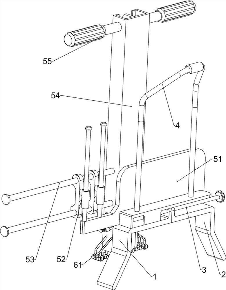
[0028] The moving assembly 5 includes a fixed plate 51, a first sliding sleeve 52, a slide bar 53, a connecting frame 54 and a second handle 55, the first extruding frame 1 is...

Embodiment 2

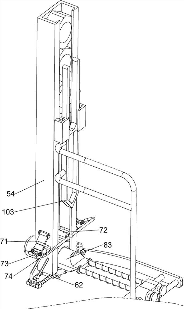
[0033] On the basis of Example 1, such as image 3 As shown, a positioning assembly 8 is also included. The positioning assembly 8 includes a guide rail 81, a second sliding sleeve 82, a positioning rod 83 and a return spring 84. The right side of the first extrusion frame 1 is connected with a guide rail 81, and the left side of the guide rail 81 is A second sliding sleeve 82 is slidably connected to the side, and a positioning rod 83 is slidably connected to the second sliding sleeve 82 , and a return spring 84 is connected between the positioning rod 83 and the second sliding sleeve 82 .

[0034]When operating the first extrusion frame 1 and the second extrusion frame 2 to clamp the steel frame 120, it is necessary to pull the positioning rod 83 to move forward, and the return spring 84 is compressed. After clamping, pull the positioning rod 83 to align The holes corresponding to each other of the two steel frames 120, if the two holes are completely corresponding, the posi...

Embodiment 3

[0036] On the basis of Example 2, such as image 3 As shown, it also includes a clamping assembly 9, the clamping assembly 9 includes a first connecting rod 91, a limit frame 92 and a second tension spring 93, the front side of the positioning rod 83 is connected with the first connecting rod 91, the first A limiting frame 92 is connected to the connecting rod 91 , and the limiting frame 92 cooperates with the sliding rod 53 , and a second tension spring 93 is connected between the first sliding sleeve 52 and the fixing plate 51 .

[0037] Initially, the second tension spring 93 is in a stretched state, and the limit frame 92 pushes against the slide bar 53. When the positioning rod 83 is pulled to move forward, the positioning rod 83 moves forward to drive the limit through the first connecting rod 91. The frame 92 moves forward, and when the limit frame 92 moves forward until it no longer touches the slide bar 53, the first sliding sleeve 52 moves upward under the action of ...


PUM


Abstract

The invention relates to a connection auxiliary device, in particular to a bolt connection auxiliary device for steel structure building construction. The technical problem to be solved by the present invention is how to design an auxiliary bolt connection equipment for steel structure building construction that is simple to operate, can improve work efficiency, and saves manpower. In order to solve the above technical problems, the present invention provides such an auxiliary bolt connection equipment for steel structure building construction, which includes: a first extruding frame, on which a second extruding frame is slidably connected; a screw rod, which is rotatably connected On the first extruding frame, the screw rod is threadedly matched with the second extruding frame; the first handle is connected to the top of the first extruding frame; and the moving assembly is arranged on the first extruding frame. The present invention assists in the connection of the steel frames through the cooperative operation of the first extruding frame, the second extruding frame, the moving assembly, the limiting assembly and the positioning assembly, so as to achieve the effect of assisting in the connection of the steel frames.

Description

technical field [0001] The invention relates to a connection auxiliary device, in particular to a bolt connection auxiliary device for steel structure building construction. Background technique [0002] With the continuous development of modern society and the improvement of people's quality of life, in modern society, many factories, light steel villas or some greenhouse buildings usually use steel structure houses, which are usually connected by steel frames. After the docking is completed, the steel frame is fixed with screws and nuts to complete the construction of the steel structure house. [0003] At present, the method of butt-joining the steel frames is usually to manually align the steel frames. After the alignment is completed, the nuts are placed on the side of the steel frame with a hole in one hand, and then the bolts are inserted from the other side of the steel frame. One side inserts and cooperates with the nut to fix the steel frame. The operation process...

Claims


Application Information

Patent Timeline
Patent Type & Authority Patents(China)
IPC IPC(8): E04B1/58E04G21/16
Inventor 李广荣
Owner 佛山市南方新联物流装备制造有限公司
Why Eureka
Try Eureka