

Reinforced concrete frame shear wall reinforcing structure
A technology of reinforced concrete and reinforcing structures, applied in the direction of walls, building components, building structures, etc., can solve problems such as being difficult to use for a long time, and achieve the effects of preventing collapse, increasing stability, and increasing stability.
- Summary
- Abstract
- Description
- Claims
- Application Information
AI Technical Summary
Problems solved by technology
Method used
Image

Examples
Embodiment Construction
[0032] In order to make the purpose, technical solution and advantages of the present invention clearer, the following will further describe the implementation of the present invention in detail in conjunction with the accompanying drawings.
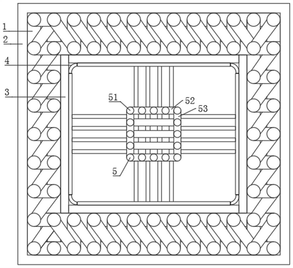
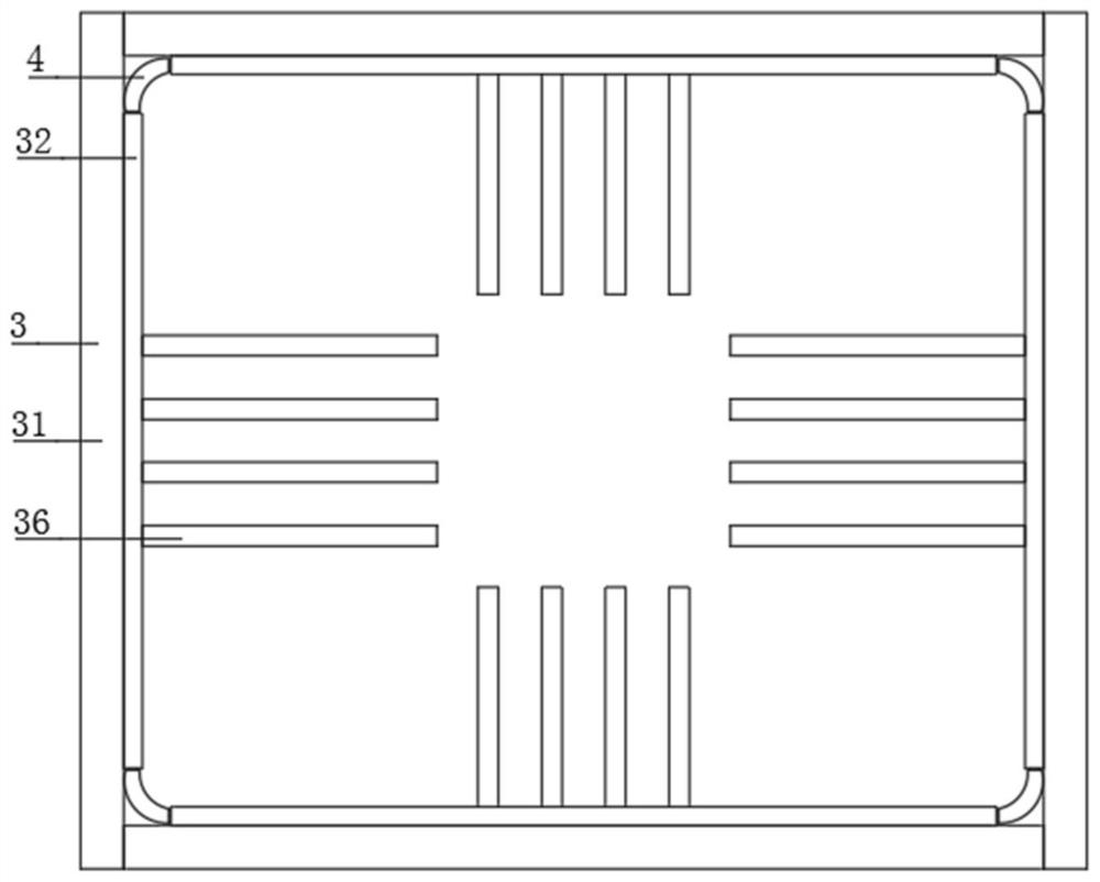
[0033] The invention provides a reinforced concrete frame shear wall reinforcement structure, which has the advantages of increasing the stability of the overall structure, and increasing the pressure resistance and service life of the overall structure. Please refer to Figure 1-6 , including reinforced concrete outer frame 1, outer wall brick 2, shear wall 3, inner corner block 4 and reinforced concrete inner frame 5;
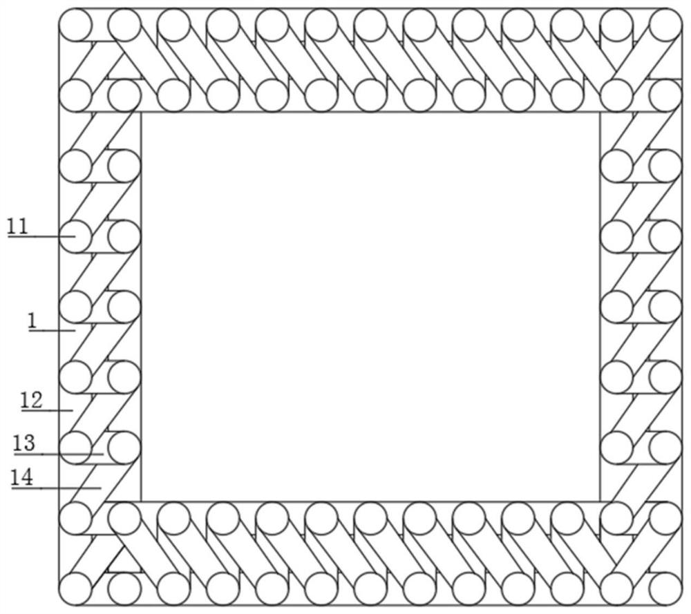
[0034] Further, the reinforced concrete outer frame 1 is provided with a shear wall 3 inside, and the reinforced concrete outer frame 1 includes outer frame vertical steel bars 11, outer frame vertical steel bars 12, outer frame horizontal steel bars 13 and outer frame oblique steel bars 14, specifically, the outer frame...
PUM
 Abstract
Description
Claims
Application Information