Grader having the cab mounted thereon

A cab and motor grader technology, which is applied in the field of motor graders, can solve the problems of obstructing the front view, the area of ​​the front window becomes smaller, and the front view becomes worse, so as to achieve the effect of improving visibility and improving the front view

Active Publication Date: 2012-01-25
KOMATSU LTD
View PDF4 Cites 0 Cited by
  • Summary
  • Abstract
  • Description
  • Claims
  • Application Information

AI Technical Summary

Problems solved by technology

Therefore, the width in front of the floor must increase
The greater the width in front of the floor, the poorer the visibility of the ground preparation road behind the scraper
[0013] On the other hand, when the cab disclosed in Patent Document 4 is adopted in order to ensure the visibility of the paved road behind the scraper, the area of ​​the front window becomes smaller.
Therefore, the pillars arranged on both sides of the front window obstruct the forward vision, which deteriorates the forward vision when driving at high speed.

Method used


Image

  • Grader having the cab mounted thereon
  • Grader having the cab mounted thereon
  • Grader having the cab mounted thereon

Examples


Embodiment 1

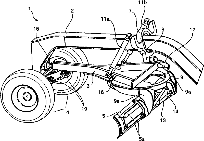
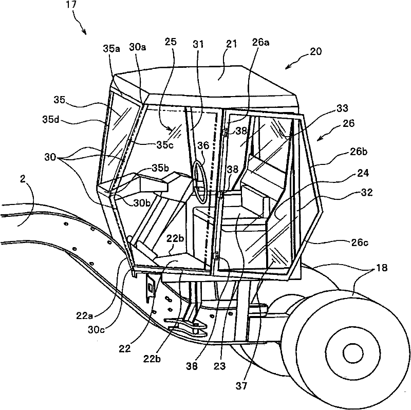
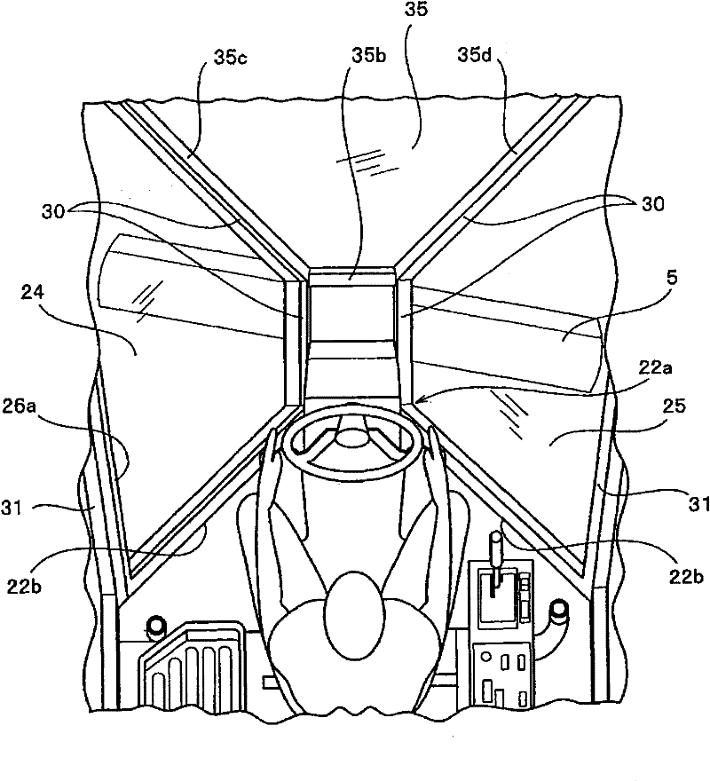
[0051] figure 1 It is an external view of the vehicle body front part of the motor grader 1 viewed from the side. That is, an external view of the front side of the front frame 2 of the motor grader 1 is shown. The appearance diagram of the operation part 17 of the car body rear portion is shown in figure 2 . In addition, the appearance of the scraper 5 viewed from the cab 20 through the floor 22 and the lower front window (32?) is given by image 3 The front perspective view of is shown.

[0052] On the front of the motor grader, such as figure 1 Shown, be provided with front wheel 4 and scraper 5 etc. that carry out operations such as cutting soil, at car body rear portion, as figure 2 Shown, be provided with rear wheel 18 and cab 20 etc. The front part of the car body is connected with the rear part of the car body through the front frame 2. Furthermore, the front frame 2 is connected to the rear part of the vehicle body, and can relatively rotate in the horizontal...


PUM


Abstract

A cab for a construction machine. A front window (35) having a trapezoidal shape, in which an upper window frame (35a) is wider than a lower window frame (35b), is placed between upper end portions of a pair of A-pillars (30). A floor (22) and a roof (21) are each formed in a shape obtained by largely cutting left and right opposite sides of a front end portion of a rectangle. The pair of A-pillars (30) and a pair of B-pillars (31), which connect between the floor (22) and the roof (21), are respectively placed at end portions on the front side and end portions on the rear side of the cut sections. Upper and lower window frames of each of a left and right pair of side front windows (24, 25) are arranged along cut sections of the floor (22) and roof (21). Side window frames for each of theside front windows (24, 25) are placed along corresponding A- and B-pillars (30, 31). One (24) of the side front windows (24, 25) is adapted to double as a door. The construction provides an operatorwith wide ranges of view from the inside of the cab (20), that is, a wide range of view for the area of work by a blade (5) and a wide range of forward view. Further, at the point of view of the operator facing forward in their seated position, the width of the front window in the left-right direction is increased and the visual range for the area of work located below the floor is increased.

Description

technical field [0001] The present invention relates to a motor grader represented by a bulldozer and a motor grader for working on road surfaces, ground, and the like. In particular, it relates to a motor grader equipped with a cab that enables confirmation of work conditions from the cab, and expands the front view and the work view to the work site. [0002] In addition, in the present invention, the front is used as a term indicating the front side of the grader, and the left-right direction is used as a term indicating the left-right direction when the cab is viewed from the rear side of the grader. In addition, regarding the vertical direction, the sky side in the vertical direction is used as the upward direction, and the ground side is used as the downward direction. Background technique [0003] A motor grader equipped with the cab of the present invention will be described. Generally speaking, a motor grader is a wheel-type civil engineering machine that prepares...

Claims


Application Information

Patent Timeline
Patent Type & Authority Patents(China)
IPC IPC(8): B62D25/08E02F9/16
CPCB62D33/0617E02F9/163
Inventor 岩片修佐竹保之武本和弘
Owner KOMATSU LTD
Why Eureka
Try Eureka