Transmitter apparatus and communication system
A technology of sending device and receiving device, which is applied in the direction of transmission system, digital transmission system, electrical components, etc., can solve problems such as inability to improve transmission efficiency, and achieve the effect of efficient communication
Inactive Publication Date: 2010-03-31
MITSUBISHI ELECTRIC CORP
1 Cites 5 Cited by
AI-Extracted Technical Summary
Problems solved by technology
In addition, in order to ensure the reliability of the expected communication accuracy, excessive data division...
Abstract
A transmitter apparatus, which constitutes, together with a receiver apparatus, a communication system for performing message communication using error detection codes, comprises a determining means that determines, based on parameters related to a probability of non-detection of message transmission errors per unit time and also based on a data length of a message, whether the transmission errornon-detection probability of the message satisfies a requirement related to the transmission error non-detection probability included in the parameters. The transmitter apparatus divides, based on a determination result of the determining means, the message such that the requirement is satisfied or adds the error detection codes to the respective divided messages and then transmits the divided messages to the receiver apparatus.
Application Domain
Error prevention
Technology Topic
Non detectionUser Error +4
Image
Examples
- Experimental program(15)
Example Embodiment
[0063] Embodiment 1
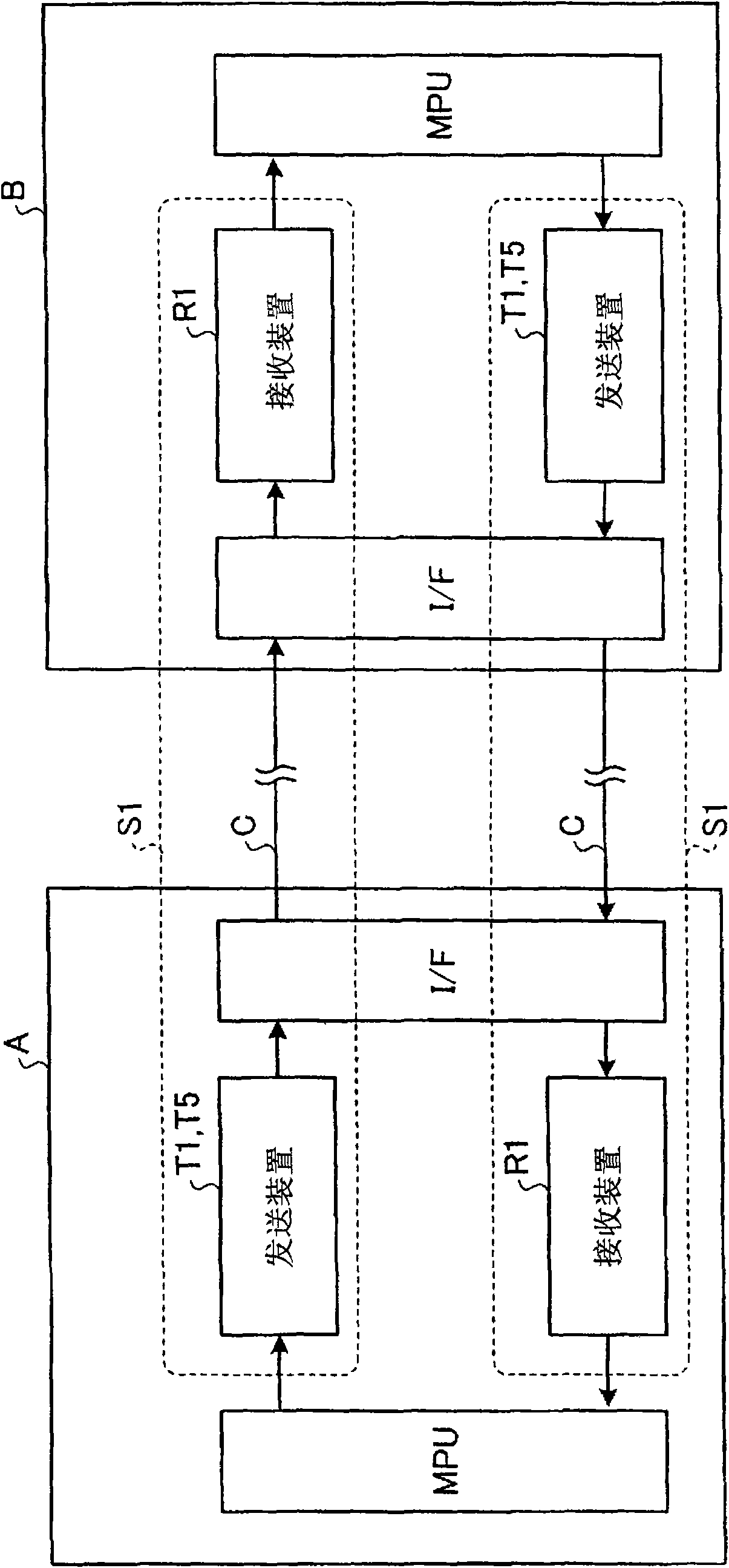
[0064] Picture 1-1 It is a figure explaining the structure of the communication system concerning Embodiment 1 of this invention. The communication system S1 according to the first embodiment is configured by connecting a transmitting device T1 and a receiving device R1 through a communication line C. in Picture 1-1 In, a communication system S1 is formed by the transmitting device T1 mounted on the device A constituting the FA (Factory Automation) and the receiving device R1 mounted on the device B constituting the FA. In addition, the transmitting device T1 mounted on the device B The device T1 and the receiving device R1 mounted on the device A constitute another communication system S1. The device A is, for example, a programmable controller (PLC) as a control device. Equipment B is, for example, a processing device that is a controlled object.
[0065] A programmable controller (PLC) (device A) as a control device has, for example, an MPU (Micro Processing Unit), which controls processing in a programmable controller (PLC), and a system program ROM (Read-Only Memory), which stores The system program used to execute the basic processing in the programmable controller (PLC); the system working RAM, which is the memory area used by the system program; the interface used to communicate with the FA device B (in the figure, marked It is the data bus I/F); user program RAM (Random AccessMemory), which stores the user program running through the programmable controller (PLC); and user data RAM, which stores the data used by the user program. The above-mentioned processing units are connected via a bus. In addition, in Picture 1-1 In the figure, the symbols other than the interface (in the figure, labeled as data bus I/F) and MPU are omitted.
[0066] In addition, the processing device (equipment B) to be controlled includes: lower-level control target equipment in the processing device such as a motor; MPU (Micro Processing Unit), which controls the processing in the processing device; and used to communicate with FA equipment B The interface for communication between (in the figure, marked as data bus I/F). The above-mentioned processing units are connected via a bus. In addition, in Picture 1-1 In the figure, the symbols other than the interface (in the figure, labeled as data bus I/F) and MPU are omitted.
[0067] Next, the communication system S1 composed of the transmitting device T1 and the receiving device R1 will be described. Figure 1-2 It is a block diagram for explaining the configuration of the transmission device T1 of the communication system S1 according to the first embodiment. The transmitting device T1 consists of a parameter input unit 1, a transmission error non-detection probability determination unit 2, a frame header/data input unit 3, a division length determination unit 4, a data division unit 5, a data CRC generation unit 6, a frame header CRC generation unit 11, The transmission data combination unit 7 and the transmission unit 8 are constituted.
[0068] First, explain the functions of each part. Before inputting the data to be transmitted to the transmitting device T1, the parameter related to the undetected probability of the information transmission error per unit time is input to the parameter input unit 1. The parameters include the target value of the undetected probability of the information transmission error per unit time, the bit error occurrence probability of the communication line, the transmission speed of the communication line, the number of information (transmission data) per unit time, and the number of connected communication devices. The parameter input unit 1 sends the input parameter to the transmission error non-detection probability determination unit 2.
[0069] After inputting the parameters to the parameter input unit 1, for example, from an application program started in the device A, the data to be transmitted is input to the frame header/data input unit 3. The header/data input unit 3 transmits the data length of the data to the division length determination unit 4, and transmits the header and data to the data division unit 5. The division length determination unit 4 sets the data length received from the frame header/data input unit 3 to the initial value of the division length (initialization of the division length), and sends the division length and data length to the transmission error non-detection probability judgment unit 2 send.
[0070] The transmission error non-detection probability judging section 2 stores a predetermined evaluation function related to the transmission error non-detection probability, and uses the evaluation function to calculate the transmission error non-detection probability (probability that the transmission error cannot be detected = error rate) Λ, and also calculates communication Other condition values required. In the first embodiment, the transmission error non-detection probability determination unit 2 is based on the data length and the division length received from the division length determination unit 4, the parameters received from the parameter input unit 1, and the code length of the CRC (generator polynomial), Calculate the transmission error undetected probability Λ. Here, the code length (generator polynomial) of the CRC uses a value determined in advance and held by the transmission error non-detection probability determination unit 2.
[0071] In addition, the transmission error non-detection probability determination unit 2 determines whether the calculated transmission error non-detection probability Λ satisfies the target value of the transmission error non-detection probability among the parameters, and notifies the division length determination unit 4 of the determination result. The determination result is either NG (the calculated transmission error undetected probability Λ does not satisfy the target value of the transmission error undetected probability) or OK (the calculated transmission error undetected probability Λ meets the target value of the transmission error undetected probability).
[0072] The evaluation function f(n, p, v, d, m) of the transmission error non-detection probability Λ per unit time is obtained, for example, using the following formula (1).
[0073] Λ=3600×R(p)×v×(m-1)...(1)
[0074] Here, v refers to the number of messages per second (the frequency of transmission), and m refers to the number of connections including the sending device.
[0075] In addition, R(p) refers to the undetected transmission error probability of each message when the bit error occurrence probability of the transmission path is p, and is usually calculated by the following formula.
[0076] R(p)=∑(e=d to n){A(n,e)×p^e ×(1-p)^(n-e)}
[0077] Here, Σ(e=d to n) represents the sum of the value of e from d to n for the formulas in the braces that follow. d refers to the characteristic value (Hamming Distance) of the error detection code. A(n, e) represents a binomial formula and forms the following formula.
[0078] (n, e)=n! ×e! /(n-e)!
[0079] N is the length of the information (the number of bits in the frame), n! Refers to the factorial of n. p^e refers to the e power of p. In addition, R(p) may use a value that takes into account the characteristics of error detection codes such as CRC.
[0080] In addition, when the division length determination unit 4 receives the determination result of the transmission error non-detection probability determination unit 2, and the determination result is NG (the calculated transmission error non-detection probability Λ does not satisfy the target value of the transmission error non-detection probability) , Shorten the division length, and notify the transmission error non-detection probability determination unit 2 again of the data length and the shortened division length. In addition, when the division length determination unit 4 receives the determination result of the transmission error non-detection probability determination unit 2 and the determination result is OK (the calculated transmission error non-detection probability Λ satisfies the target value of the transmission error non-detection probability), The division length is sent to the data division unit 5.
[0081] The data segmentation unit 5 stores the segmentation length received from the segmentation length determination unit 4 in the header received from the header/data input unit 3, and sends the header to the header CRC generation unit 11 and the transmission data combination unit 7 . In addition, the data dividing unit 5 divides the data received from the frame header/data input unit 3 based on the divided length received from the divided length determining unit 4, and combines the divided data to the data CRC generating unit 6 and the transmission data. Section 7 sends.
[0082] The data CRC generating unit 6 calculates and generates a data CRC for the divided data received from the data dividing unit 5 by using a predetermined and stored CRC generating polynomial, and sends it to the transmission data combining unit 7. The header CRC generating unit 11 calculates and generates the header CRC for the header received from the data dividing unit 5 using a predetermined and stored CRC generator polynomial, and sends it to the transmission data combining unit 7.
[0083] The transmission data combining unit 7 combines the frame header and the divided data received from the data dividing unit 5, the frame header CRC received from the frame header CRC generating unit 11, and the data CRC received from the data CRC generating unit 6 to form transmission data (Information) and send it to the sending unit 8.
[0084] The transmission unit 8 transmits the transmission data (information) received from the transmission data combination unit 7 to the communication line C. in Figure 1-3 An example of the structure of combined transmission data (information) is shown in. Figure 1-3 The transmission data (information) shown is the transmission data in the case of dividing the data into n parts, including the frame header, the frame header CRC for the frame header, the divided data 1, the data CRC for data 1, 1, after division Data 2 for data 2, data CRC 2 for data 2 ... divided into data n and data CRC n for data n.
[0085] Below, refer to Figure 1-4 The transmission processing in the transmission device T1 will be described. Figure 1-4 It is a flowchart for explaining the processing of the transmission device T1 according to the first embodiment. First, input parameters to the parameter input unit 1 (step S1). The parameters are, for example, connected to a computer such as a personal computer with the transmitting device T1, and input using the personal computer or the like. The parameter input unit 1 sends the input parameter to the transmission error non-detection probability determination unit 2.
[0086] After inputting the parameters to the parameter input unit 1, if the header/data input unit 3 inputs the data to be sent to the receiving device R1 from an application started in the device A, the header/data input unit 3 will The data length of the data is sent to the division length determination unit 4, and the frame header and data are sent to the data division unit 5.
[0087] After receiving the data length from the frame header/data input unit 3, the division length determination unit 4 sets (initializes) the received data length to the initial value of the division length (step S2). Then, the division length determination unit 4 transmits the division length and the data length to the transmission error non-detection probability determination unit 2. The transmission error non-detection probability judging unit 2 calculates the transmission error non-detection probability Λ based on the data length and the division length received from the division length determination unit 4, the parameters received from the parameter input unit 1, and the CRC code length (generator polynomial) (in Figure 1-4 Marked as the error rate. The same applies in the subsequent drawings. ) (Step S3).
[0088] Then, the transmission error non-detection probability determination unit 2 determines whether the calculated transmission error non-detection probability Λ satisfies the target value of the transmission error non-detection probability among the parameters (step S4), and notifies the division length determination unit 4 of the determination result . As a result of the judgment, it is notified of NG (the calculated transmission error undetected probability Λ does not satisfy the target value of the transmission error undetected probability) or OK (the calculated transmission error undetected probability Λ meets the target value of the transmission error undetected probability) One.
[0089] If the received judgment result is NG (step S4 is negative), the division length determination unit 4 shortens the division length, and again notifies the transmission error non-detection probability determination unit 2 of the data length and the shortened division length (step S5 ), start again from step S3. In addition, when the received determination result is OK (YES in step S4), the division length determination unit 4 adopts the division length at this time, and sends the division length to the data division unit 5.
[0090] Then, the data division unit 5 stores the division length received from the division length determination unit 4 in the header containing information such as the address of the information received from the header/data input unit 3 (step S6). Then, the data dividing unit 5 transmits the header to the header CRC generating unit 11 and the transmission data combining unit 7. The header CRC generating unit 11 generates a header CRC using a predetermined and stored CRC generator polynomial for the header received from the data dividing unit 5 (step S7), and transmits it to the transmission data combining unit 7.
[0091] In addition, the data dividing unit 5 divides and extracts the data received from the frame header/data input unit 3 according to the divided length based on the divided length received from the divided length determining unit 4 (step S8). Then, the data dividing unit 5 sends the divided data to the data CRC generating unit 6 and the transmission data combining unit 7. The data CRC generating unit 6 calculates and generates a data CRC using a predetermined and stored CRC generating polynomial for the divided data received from the data dividing unit 5 (step S9), and sends it to the transmission data combining unit 7.
[0092] The transmission data combining unit 7 combines the frame header and the divided data received from the data dividing unit 5, the frame header CRC received from the frame header CRC generating unit 11, and the data CRC received from the data CRC generating unit 6 into transmission data. (Information) (Step S10). The transmission data combination unit 7 determines whether the extraction (combination) of the divided data received from the data division unit 5 has been completed (step S11).
[0093] When it is determined that it is not completed (step S11 is negative), the process returns to step S8, and the execution is repeated until the extraction is completed. In addition, when it is determined that it has been completed (step S11 is affirmative), the transmission data combination unit 7 transmits the transmission data (information) to the transmission unit 8. The transmission unit 8 transmits the transmission data (information) received from the transmission data combination unit 7 to the communication line C, thereby ending a series of processing (step S12). The transmission data (information) sent from the transmission device T1 is transmitted to the reception device R1 via the communication line C.
[0094] Every time data is input from the application program started in the device A, the transmitting device T1 repeats the processing from step S1 to step S12. However, if the parameters are the same after the second time, the processing of step S1 may be omitted.
[0095] Figure 1-5 It is a block diagram for explaining the configuration of the receiving device R1 of the communication system S according to the first embodiment. The receiving device R1 is composed of a receiving unit 21, a division length determining unit 22, a data dividing unit 23, a data CRC determining unit 24, a data combining unit 25, a data output unit 26, and a frame header CRC determining unit 29.
[0096] The receiving unit 21 receives from the communication line such as Figure 1-3 The received data (information) shown is sent to the division length judgment unit 22. The division length determining unit 22 obtains the header and header CRC from the received data received by the receiving unit 21, and sends the header and header CRC to the header CRC determining unit 29. In addition, the division length judgment unit 22 receives the judgment result of the frame header CRC judgment unit 29, and obtains the division length from the frame header only when the judgment result is OK (the check result is correct), and divides the received data and the division length into the data. Section 23 sends.
[0097] The header CRC determination unit 29 checks the header CRC of the header received by the division length determination unit 22 using a predetermined and stored generator polynomial, and notifies the division length determination unit 22 of the determination result. The judgment result is either NG (the verification result is incorrect) or OK (the verification result is correct).
[0098] The data division unit 23 divides the received data according to the length obtained by adding the division length received from the division length judgment unit 22 and the code length of the data CRC determined and stored in advance, and divides the whole, namely the divided data and the data The CRC is sent to the data CRC determination unit 24. In addition, the data dividing unit 23 sends the divided data as a data portion to the data combining unit 25.
[0099] The data CRC determination unit 24 checks the data CRC using a predetermined and stored generator polynomial, and notifies the data combination unit 25 of the determination result. The judgment result is either NG (the verification result is incorrect) or OK (the verification result is correct).
[0100] The data combination unit 25 receives the judgment result sent from the data CRC judgment unit 24, and only when the judgment results of all the divided data are OK (the check result is correct), the divided data is combined and sent to the data output unit 26. The data output unit 26 receives the data sent from the data combination unit 25, and outputs the data to an application program or the like started in the device B.
[0101] Below, refer to Figure 1-6 , The receiving process in the receiving device R1 will be explained. Figure 1-6 It is a flowchart for explaining the processing of the receiving device R1 according to the first embodiment. First, the receiving unit 21 of the receiving device R1 receives received data (information) from the communication line (step S31), and transmits the received data (information) to the division length determining unit 22. The division length determining unit 22 obtains the header and header CRC from the received data received by the receiving unit 21, and sends the header and header CRC to the header CRC determining unit 29.
[0102] The header CRC determination unit 29 uses a predetermined and stored generator polynomial to check the header CRC based on the header (step S32), and notifies the division length determination unit 22 of the determination result. The judgment result is either NG (the verification result is incorrect) or OK (the verification result is correct).
[0103] When the division length determination unit 22 receives the determination result of the frame header CRC determination unit 29, and the determination result is NG (the check result is incorrect) (step S32 is negative), it determines that an error has been detected in the received data ( Step S33), a series of processing ends. On the other hand, when the determination result of the frame header CRC determination unit 29 is received and the determination result is OK (the check result is correct) (step S32 is affirmative), the division length determination unit 22 obtains the division length from the frame header ( Step S34), the received data and the division length are sent to the data division unit 23.
[0104] The data dividing unit 23 divides and reads the received data according to the length obtained by adding the divided length received from the divided length determining unit 22 and the code length of the predetermined data CRC (step S35), and divides the divided data and The data CRC is sent to the data CRC determination unit 24. In addition, the data dividing unit 23 sends the divided data as a data portion to the data combining unit 25.
[0105] The data CRC determination unit 24 checks the data CRC using a predetermined generator polynomial (step S36), and notifies the data combination unit 25 of the determination result. The judgment result is either NG (the verification result is incorrect) or OK (the verification result is correct).
[0106] When the data combination unit 25 receives the determination result of the data CRC determination unit 24, and the determination result is NG (the check result is incorrect) (step S36 is negative), it determines that an error has been detected in the received data (step S33 ) To end a series of processing. On the other hand, when the judgment result of the data CRC judgment unit 24 is received and the judgment result is OK (the check result is correct) (step S36 is affirmative), the data combination unit 25 judges whether the data CRC of all the divided data is correct. The verification has been completed (step S37).
[0107] When it is determined that the data CRC check of all the divided data has not been completely completed (step S37: No), the data combination unit 25 sends information indicating that the check result is correct to the data CRC determination unit 24, and returns to step S35. After receiving the information, the data CRC determination unit 24 checks the CRC of the next divided data (step S35). Then, the process of step S35 to step S37 is repeatedly executed until the data CRC of all the divided data is checked.
[0108] On the other hand, when it is determined that the CRC calculation of all the divided data is correct, and the data CRC of all the divided data has been checked (YES in step S37), the data combination unit 25 determines that the data has been received normally (step S38) , The divided data is combined and sent to the data output unit 26. The data output unit 26 receives the data sent from the data combination unit 25, and outputs the data to an application program or the like started in the device B, thereby ending a series of processing.
[0109] As described above, in the transmission device T1 (communication system S) according to the first embodiment, it is possible to divide data and transmit information so as to ensure the upper limit of the undetected probability of information transmission errors per unit time. Thereby, it is possible to suppress the undetected probability of an information transmission error to be less than or equal to the desired target value, and to ensure the reliability of the desired communication accuracy rate to perform communication. In addition, since there is no need to perform excessive data division, efficient communication can be performed.
[0110] In addition, in the above description, the case where the transmission error non-detection probability determination unit 2 changes the division length and repeats the calculation until the calculated transmission error non-detection probability Λ satisfies the target value of the transmission error non-detection probability among the parameters. However, the aforementioned evaluation function (1) may be modified to directly obtain the segmentation length that satisfies the target value of the undetected probability of transmission error in the parameter.
[0111] The segmentation length (the number of bits of the frame) that meets the target value of the undetected probability of transmission error in the parameter can be calculated by the evaluation function g(m, p, v, d, Λ). The evaluation function g(m, p, v, d, Λ) is derived by transforming the above evaluation function f(m, p, v, d, n). In this case, since the segmentation length (the number of bits of the frame) corresponding to the target value of the transmission error undetected probability in the parameter can be calculated, it is sufficient that the segmentation length adopts a value less than or equal to the calculated segmentation length.
Example Embodiment
[0112] Embodiment 2
[0113] diagram 2-1 It is a figure explaining the structure of the communication system concerning Embodiment 2 of this invention. The communication system S2 according to the second embodiment is configured by connecting a transmitting device T2 and a receiving device R2 via a communication line C. in diagram 2-1 , A communication system S2 is formed by the transmitting device T2 mounted on the device A constituting the FA and the receiving device R2 mounted on the device B constituting the FA. In addition, the transmitting device T2 mounted on the device B and the receiving device R2 mounted on the device B The receiving device R2 on the device A constitutes another communication system S. In addition, since the device A, the device B, etc. are the same as those in the first embodiment, the description in the first embodiment is referred to, and the description is omitted here.
[0114] Figure 2-2 It is a block diagram for explaining the configuration of the transmission device T2 of the communication system S2 according to the second embodiment. The transmitting device T2 consists of a parameter input unit 1, a transmission error non-detection probability determination unit 2, a frame header/data input unit 3, a code length determination unit 9, a data division unit 5, a data CRC generation unit 6, a frame header CRC generation unit 11, The transmission data combination unit 7 and the transmission unit 8 are constituted. In addition, the same reference numerals as in the case of the first embodiment are assigned to the same configuration as that of the first embodiment.
[0115] First, explain the functions of each part. Before inputting the data to be transmitted to the transmission device T2, the parameter input unit 1 inputs the parameter related to the undetected probability of the information transmission error per unit time. The parameters include the target value of the undetected probability of the information transmission error per unit time, the bit error occurrence probability of the communication line, the transmission speed of the communication line, the number of information (transmission data) per unit time, and the number of connected communication devices. The parameter input unit 1 sends the input parameter to the transmission error non-detection probability determination unit 2.
[0116] In addition, the transmitting device T2 has previously stored a code correspondence table 31 common to the receiving device R2. Figure 2-3 It is a diagram showing an example of the code correspondence table 31. In the code correspondence table 31, the code identification number, code length, and CRC generator polynomial are stored in a list. Here, the code length is used as the code identifier.
[0117] After inputting the parameters to the parameter input unit 1, for example, from an application program started in the device A, the data to be transmitted is input to the frame header/data input unit 3. The header/data input unit 3 sends the data length of the data to the code length determination unit 9, and sends the header and data to the data dividing unit 5. The code length determination unit 9 sets the code length (for example, 16 bits) of the standard generator polynomial to the initial value of the code length (initialization of the code length) according to the code correspondence table 31, and sends the code length and data length to the transmission error undetected The probability determination unit 2 sends it.
[0118] The transmission error non-detection probability judging unit 2 stores a predetermined evaluation function related to the transmission error non-detection probability, uses the evaluation function to calculate the transmission error non-detection probability Λ, and also calculates other condition values required for communication. In the second embodiment, on the basis of the data length and code length received from the code length determination unit 9, based on the parameters received from the parameter input unit 1 and the division length, the probability of undetected transmission error (the transmission error cannot be detected is calculated). Probability=error rate)Λ. Here, the division length uses a value determined in advance and held by the transmission error non-detection probability determination unit 2.
[0119] In addition, the transmission error non-detection probability judging unit 2 determines whether the calculated transmission error non-detection probability Λ satisfies the transmission error non-detection probability target value in the parameter (whether it is less than or equal to the transmission error non-detection probability target value), and determines The result is notified to the code length determination unit 9. The judgment result is NG (the calculated transmission error undetected probability Λ is higher than the target value of the transmission error undetected probability) or OK (the calculated transmission error undetected probability Λ is less than or equal to the target value of the transmission error undetected probability) One.
[0120] In addition, the code length determination unit 9 receives the determination result of the transmission error non-detection probability determination unit 2, and the determination result is NG (the calculated transmission error non-detection probability Λ does not meet the target value of the transmission error non-detection probability (ratio When the undetected probability target value is high)), a longer generator polynomial is selected from the code correspondence table 31 to increase the code length, and the transmission error undetected probability determination unit 2 is notified of the data length and code length again. In addition, the code length determination unit 9 receives the determination result of the transmission error non-detection probability determination unit 2 and the determination result is OK (the calculated transmission error non-detection probability Λ satisfies the target value of the transmission error non-detection probability (calculated transmission When the error non-detection probability Λ is less than or equal to the transmission error non-detection probability target value)), the code length is transmitted to the data dividing unit 5.
[0121] The data dividing unit 5 stores the code length received from the code length determining unit 9 in the frame header received from the frame header/data input unit 3, and sends the frame header to the header CRC generating unit 11 and the transmission data combining unit 7 send. In addition, the data dividing unit 5 divides the data received from the frame header and the data input unit 3 based on a predetermined and stored division length, transmits the code length and the divided data to the data CRC generating unit 6, and divides the data. The subsequent data is sent to the sending data combining unit 7.
[0122] The data CRC generating unit 6 refers to the code correspondence table 31 based on the code length and the divided data received from the data dividing unit 5, generates a data CRC using a generator polynomial corresponding to the code length, and sends it to the transmission data combining unit 7. The header CRC generating unit 11 calculates and generates the header CRC based on the header received from the data dividing unit 5 using a predetermined and stored CRC generator polynomial, and sends it to the transmission data combining unit 7.
[0123] The transmission data combining unit 7 combines the frame header and the divided data received from the data dividing unit 5, the frame header CRC received from the frame header CRC generating unit 11, and the data CRC received from the data CRC generating unit 6 to form transmission data (Information) and send it to the sending unit 8.
[0124] The transmission unit 8 transmits the transmission data (information) received from the transmission data combination unit 7 to the communication line C. Figure 1-3 An illustrative configuration example of transmission data (information) generated by the combination is shown.
[0125] Below, refer to Figure 2-4 The transmission processing in the transmission device T2 will be described. Figure 2-4 It is a flowchart for explaining the processing of the transmission device T2 according to the second embodiment. First, input parameters to the parameter input unit 1 (step S1). The parameters are, for example, connected to a computer such as a personal computer with the transmitting device T2, and inputted using the personal computer or the like. The parameter input unit 1 sends the input parameter to the transmission error non-detection probability determination unit 2.
[0126] After inputting the parameters to the parameter input unit 1, if, for example, the application program started in the device A inputs the data to be sent to the receiving device R2 to the header/data input unit 3, the header/data input unit 3 will The data length of the data is sent to the division length determination unit 4, and the frame header and data are sent to the data division unit 5.
[0127] In addition, the code length determining unit 9 sets the code length (for example, 16 bits) of the standard generator polynomial as the initial value of the code length (initialization of the code length) based on the code correspondence table 31, and transmits the code length and data length to The error non-detection probability determination unit 2 transmits (step S13).
[0128] The transmission error undetected probability judging section 2 calculates the transmission error undetected probability (error rate) based on the data length and code length received from the code length determining section 9, based on the parameters received from the parameter input section 1 and the division length. )Λ(Step S14). Here, the division length uses a value determined in advance and held by the transmission error non-detection probability determination unit 2.
[0129] Then, the transmission error non-detection probability judging unit 2 judges whether the calculated transmission error non-detection probability Λ satisfies the transmission error non-detection probability target value in the parameter (step S4), and sends the judgment result to the code length determining unit 9 Notice. As a result of the judgment, NG (the calculated transmission error undetected probability Λ is higher than the target value of the transmission error undetected probability) or OK (the calculated transmission error undetected probability Λ is less than or equal to the target value of the transmission error undetected probability) One of them.
[0130] When the received judgment result is NG (No in step S4), the code length determination unit 9 selects a longer generator polynomial from the code correspondence table 31 to increase the code length, and sends it to the transmission error undetected probability judgment unit again 2 Notify the data length and the increased code length (step S15), and start again from step S13. In addition, when the received determination result is OK (step S4 is affirmative), the code length determining unit 9 adopts the code length at this time, and transmits the code length to the data dividing unit 5.
[0131] Then, the data dividing unit 5 stores the code length received from the code length determining unit 9 in the header containing information such as the address of the information received from the header/data input unit 3 (step S16). Then, the data dividing unit 5 transmits the header to the header CRC generating unit 11 and the transmission data combining unit 7. The header CRC generating unit 11 generates a header CRC based on the header received from the data dividing unit 5 using a predetermined and stored CRC generator polynomial (step S7), and sends it to the transmission data combining unit 7.
[0132] In addition, the data dividing unit 5 divides and extracts the data received from the frame header/data input unit 3 based on the divided length determined and stored in advance (step S8). Then, the data dividing unit 5 sends the code length and the divided data to the data CRC generating unit 6, and sends the divided data to the transmission data combining unit 7. The data CRC generating unit 6 refers to the code correspondence table 31 based on the code length and the divided data received from the data dividing unit 5, calculates the generated data CRC using the generator polynomial corresponding to the code length (step S9), and sends it to the data combining unit 7 send.
[0133] The transmission data combining unit 7 combines the frame header and the divided data received from the data dividing unit 5, the frame header CRC received from the frame header CRC generating unit 11, and the data CRC received from the data CRC generating unit 6 to form transmission data (Information) (Step S10). The transmission data combination unit 7 determines whether the extraction (combination) of the divided data received from the data division unit 5 has been completed (step S11).
[0134] When it is determined that it is not completed (step S11 is negative), the process returns to step S8, and the execution is repeated until the extraction is completed. In addition, when it is determined that it has been completed (step S11 is affirmative), the transmission data combination unit 7 transmits the transmission data (information) to the transmission unit 8. The transmission unit 8 transmits the transmission data (information) received from the transmission data combination unit 7 to the communication line C, thereby ending a series of processing (step S12). The transmission data (information) transmitted from the transmission device T1 is transmitted to the reception device R1 via the communication line C.
[0135] Every time data is input from the application program started in the device A, the transmission device T2 repeats the processing from step S1 to step S12. However, if the parameters are the same after the second time, the processing of step S1 may be omitted.
[0136] Figure 2-5 It is a block diagram for explaining the configuration of the receiving device R2 of the communication system S2 according to the second embodiment. The receiving device R2 is composed of a receiving unit 21, a code length determining unit 27, a data dividing unit 23, a data CRC determining unit 24, a data combining unit 25, a data output unit 26, and a frame header CRC determining unit 29.
[0137] In addition, the receiving device R2 previously stores a code correspondence table 31 common to the transmitting device T2. In the code correspondence table 31, the code identification number, code length, and CRC generator polynomial are stored in a list. Here, the code length is used as the code identifier.
[0138] The receiving unit 21 receives from the communication line such as Figure 1-3 The received data (information) shown is sent to the code length judgment unit 27. The code length determination unit 27 obtains the header and header CRC from the received data received by the receiving unit 21, and sends the header and header CRC to the header CRC determination unit 29. In addition, the code length judgment unit 27 receives the judgment result of the frame header CRC judgment unit 29, and only when the judgment result is OK (check result is correct), obtains the code length from the frame header, and divides the received data and the code length into data Section 23 sends.
[0139] The header CRC judgment unit 29 checks the header CRC using a predetermined and stored generator polynomial based on the header received from the code length judgment unit 27 and notifies the code length judgment unit 27 of the judgment result. The judgment result is either NG (the verification result is incorrect) or OK (the verification result is correct).
[0140] The data dividing unit 23 divides the received data according to the length obtained by adding the divided length determined and stored in advance and the code length received from the code length judging unit 27, and divides the whole, namely the divided data, the data CRC, and the code. The long is sent to the data CRC determination unit 24. In addition, the data dividing unit 23 sends the divided data as a data portion to the data combining unit 25.
[0141] The data CRC judging unit 24 checks the data CRC using the generator polynomial corresponding to the code length by referring to the code correspondence table 31 based on the code length and the divided data received from the data dividing unit 23, and sends the judgment result to the data combining unit 25 Make notifications. The judgment result is either NG (the verification result is incorrect) or OK (the verification result is correct).
[0142] The data combination unit 25 receives the judgment result sent from the data CRC judgment unit 24, and only when the judgment results of all the divided data are OK (the check result is correct), the divided data is combined and sent to the data output unit 26. The data output unit 26 receives the data sent from the data combination unit 25, and outputs the data to an application program or the like started in the device B.
[0143] Below, refer to Figure 2-6 , The receiving process in the receiving device R2 will be explained. Figure 2-6 It is a flowchart for explaining the processing of the receiving device R2 according to the second embodiment. First, the receiving unit 21 of the receiving device R2 receives received data (information) from the communication line (step S31), and transmits the received data (information) to the code length determining unit 27. The code length determining unit 27 obtains the frame header and the header CRC based on the received data received from the receiving unit 21, and transmits the frame header and the header CRC to the header CRC determining unit 29.
[0144] The header CRC judging unit 29 uses a predetermined and stored generator polynomial to verify the header CRC based on the header received from the code length judging unit 27 (step S32), and sends the judgment result to the code length judging unit 27 Notice. The judgment result is either NG (the verification result is incorrect) or OK (the verification result is correct).
[0145] When the code length judging unit 27 receives the judgment result of the frame header CRC judging unit 29, and the judgment result is NG (the check result is incorrect) (step S32 is negative), it judges that an error has been detected in the received data ( Step S33), a series of processing ends. On the other hand, when the determination result of the frame header CRC determination unit 29 is received and the determination result is OK (the check result is correct) (step S32 is affirmative), the code length determination unit 27 obtains the division length from the frame header (Step S39) The received data and the code length are sent to the data dividing unit 23.
[0146] The data dividing unit 23 divides and reads the received data according to the length obtained by adding the predetermined divided length and the code length received from the code length determining unit 27 (step S35), and divides the divided data and the data The CRC and the code length are sent to the data CRC determination unit 24. In addition, the data dividing unit 23 sends the divided data as a data portion to the data combining unit 25.
[0147] The data CRC judging unit 24 checks the CRC of the divided data by referring to the code correspondence table 31 based on the code length and the divided data received from the data dividing unit 23 and using a generator polynomial corresponding to the code length obtained from the frame header ( Step S36), and notify the data combination unit 25 of the determination result. The judgment result is either NG (the verification result is incorrect) or OK (the verification result is correct).
[0148] When the data combination unit 25 receives the determination result of the data CRC determination unit 24, and the determination result is NG (the check result is incorrect) (step S36 is negative), it determines that an error has been detected in the received data (step S33 ) To end a series of processing. On the other hand, when the judgment result of the data CRC judgment unit 24 is received and the judgment result is OK (the check result is correct) (step S36 is affirmative), the data combination unit 25 judges whether the data CRC of all the divided data is correct. The verification has been completed (step S37).
[0149] When it is determined that the data CRC check of all the divided data has not been completely completed (step S37: No), the data combination unit 25 sends information indicating that the check result is correct to the data CRC determination unit 24, and returns to step S35. After receiving the information, the data CRC determination unit 24 checks the CRC of the next divided data (step S35). Then, the process of step S35 to step S37 is repeatedly executed until the data CRC of all the divided data is checked.
[0150] On the other hand, when it is determined that the CRC calculation of all the divided data is correct, and the data CRC of all the divided data has been checked (YES in step S37), the data combination unit 25 determines that the data has been received normally (step S38) , The divided data is combined and sent to the data output unit 26. The data output unit 26 receives the data sent from the data combination unit 25, and outputs the data to an application program or the like started in the device B, thereby ending a series of processing.
[0151] As described above, in the transmission device T2 (communication system S2) according to the second embodiment, the data CRC can be added to transmit information so as to ensure the upper limit of the undetected probability of information transmission errors per unit time. Thereby, it is possible to suppress the undetected probability of an information transmission error to be less than or equal to the desired target value, and to ensure the reliability of the desired communication accuracy rate to perform communication. In addition, since there is no need to perform excessive coding, efficient communication can be performed.
[0152] In addition, in the above description, the case where the transmission error non-detection probability determination unit 2 changes the code length and repeats calculations until the calculated transmission error non-detection probability Λ satisfies the target value of the transmission error non-detection probability among the parameters. However, the aforementioned evaluation function (1) may be modified to directly obtain the code length (d: characteristic value of the error detection code) that satisfies the target value of the transmission error undetected probability in the parameter.
[0153] The code length that satisfies the target value of the undetected probability of transmission error in the parameter can be calculated by the evaluation function h(m, p, v, n, Λ). The evaluation function h (m, p, v, n, Λ) is derived by transforming the above evaluation function f (m, p, v, d, Λ). In this case, since the code length corresponding to the target value of the undetected probability of transmission error in the parameter can be calculated, it is only necessary that the code length adopts a value greater than or equal to the calculated code length.
Example Embodiment
[0154] Embodiment 3
[0155] Figure 3-1 It is a figure explaining the structure of the communication system concerning Embodiment 3 of this invention. The communication system S3 according to the third embodiment is configured by connecting a transmitting device T3 and a receiving device R3 through a communication line C. in Figure 3-1 In the communication system S3, a transmission device T3 mounted on the device A constituting the FA and a receiving device R3 mounted on the device B constituting the FA constitute a communication system S3. In addition, a communication system S3 is constituted by the transmitting device T3 mounted on the device B and The receiving device R3 on the device A constitutes another communication system S3. In addition, since the device A, the device B, etc. are the same as those in the first embodiment, the description in the first embodiment is referred to, and the description is omitted here.
[0156] Figure 3-2 It is a block diagram for explaining the configuration of the transmission device T3 of the communication system S3 according to the second embodiment. The transmitting device T3 consists of a parameter input unit 1, a transmission error non-detection probability determination unit 2, a frame header/data input unit 3, a division length/code length determination unit 10, a data division unit 5, a data CRC generation unit 6, and a frame header CRC generation The unit 11, the transmission data combination unit 7, and the transmission unit 8 are constituted. In addition, the same reference numerals as in the case of the first embodiment are assigned to the same configuration as that of the first embodiment.
[0157] First, explain the functions of each part. Before inputting the data to be transmitted to the transmitting device T1, the parameter related to the undetected probability of the information transmission error per unit time is input to the parameter input unit 1. The parameters include the target value of the undetected probability of the information transmission error per unit time, the bit error occurrence probability of the communication line, the transmission speed of the communication line, the number of information (transmission data) per unit time, and the number of connected communication devices. The parameter input unit 1 sends the input parameter to the transmission error non-detection probability determination unit 2.
[0158] In addition, the transmitting device T3 has a code correspondence table 31 common to the receiving device R3 (refer to Figure 2-3 ). In the code correspondence table 31, the code identification number, code length, and CRC generator polynomial are stored in a list. Here, the code length is used as the code identifier.
[0159] After inputting the parameters to the parameter input unit 1, for example, from an application program started in the device A, the data to be transmitted is input to the frame header/data input unit 3. The header/data input unit 3 transmits the data length of the data to the division length/code length determination unit 10, and transmits the header and data to the data division unit 5. The division length/code length determination unit 10 sets the data length received from the frame header/data input unit 3 to the initial value of the division length (initialization of the division length), and calculates the code length of the standard generator polynomial according to the code correspondence table 31 (For example, 16 bits) is set as the initial value of the code length (initialization of the code length). Then, the division length/code length determination unit 10 transmits the division length, code length, and data length to the transmission error non-detection probability determination unit 2.
[0160] The transmission error non-detection probability judging unit 2 stores a predetermined evaluation function related to the transmission error non-detection probability, uses the evaluation function to calculate the transmission error non-detection probability Λ, and also calculates other condition values required for communication. In the third embodiment, the transmission error non-detection probability determination unit 2 is based on the data length and code length received from the division length/code length determination unit 10, based on the parameters received from the parameter input unit 1 and the subdivision length · The division length received by the code length determining unit 10 calculates the transmission error undetected probability (probability that the transmission error cannot be detected=error rate) Λ.
[0161] In addition, the transmission error non-detection probability judging unit 2 determines whether the calculated transmission error non-detection probability Λ satisfies the transmission error non-detection probability target value in the parameter (whether it is less than or equal to the transmission error non-detection probability target value), and determines The result is notified to the division length/code length determination unit 10. The judgment result is NG (the calculated transmission error undetected probability Λ is higher than the target value of the transmission error undetected probability) or OK (the calculated transmission error undetected probability Λ is less than or equal to the target value of the transmission error undetected probability) One.
[0162] In addition, the division length/code length determination unit 10 receives the determination result of the transmission error non-detection probability determination unit 2 and the determination result is NG (the calculated transmission error non-detection probability Λ does not satisfy the transmission error non-detection probability target value ( If it is higher than the transmission error undetected probability target value)), shorten the division length, or select a longer generator polynomial from the code correspondence table 31 to increase the code length, and notify the transmission error undetected probability determination unit 2 again of the data Length, split length and code length. In addition, the code length determination unit 9 receives the determination result of the transmission error non-detection probability determination unit 2 and the determination result is OK (the calculated transmission error non-detection probability Λ satisfies the target value of the transmission error non-detection probability (calculated transmission When the error non-detection probability Λ is less than or equal to the transmission error non-detection probability target value)), the division length and the code length are transmitted to the data division unit 5.
[0163] The data division unit 5 stores the division length and code length received from the division length/code length determination unit 10 in the frame header received from the frame header/data input unit 3, and sends the frame header to the header CRC generating unit 11 and the transmission data combination unit 7 transmits. In addition, the data dividing unit 5 divides the data received from the frame header/data input unit 3 based on the divided length received from the divided length/code length determining unit 10, and generates the code length and the divided data into the data CRC. The unit 6 sends and sends the divided data to the transmission data combination unit 7.
[0164] The data CRC generating unit 6 refers to the code correspondence table 31 based on the code length and the divided data received from the data dividing unit 5, generates a data CRC using a generator polynomial corresponding to the code length, and sends it to the transmission data combining unit 7. The header CRC generating unit 11 calculates and generates the header CRC based on the header received from the data dividing unit 5 using a predetermined and stored CRC generator polynomial, and sends it to the transmission data combining unit 7.
[0165] The transmission data combining unit 7 combines the frame header and the divided data received from the data dividing unit 5, the frame header CRC received from the frame header CRC generating unit 11, and the data CRC received from the data CRC generating unit 6 into transmission data. (Information) and send it to the sending unit 8.
[0166] The transmission unit 8 transmits the transmission data (information) received from the transmission data combination unit 7 to the communication line C. Figure 1-3 An illustrative configuration example of transmission data (information) generated by the combination is shown.
[0167] Below, refer to Figure 3-3 The transmission processing in the transmission device T3 will be described. Figure 3-3 It is a flowchart for explaining the processing of the transmission device T3 according to the third embodiment. First, input parameters to the parameter input unit 1 (step S1). The parameters are, for example, connected to a computer such as a personal computer with the transmitting device T3, and inputted using the personal computer or the like. The parameter input unit 1 sends the input parameter to the transmission error non-detection probability determination unit 2.
[0168] After inputting parameters into the parameter input unit 1, if, for example, the application program started in the device A inputs the data to be sent to the receiving device R3 to the header/data input unit 3, the header/data input unit 3 will The data length of the data is sent to the division length determination unit 4, and the frame header and data are sent to the data division unit 5.
[0169] After receiving the data length from the frame header and data input unit 3, the division length/code length determination unit 10 sets (initializes) the received data length to the initial value of the division length, and generates the standard according to the code correspondence table 31 The code length (for example, 16 bits) of the polynomial is set to the initial value of the code length (initialization of the code length) (step S17). Then, the division length/code length determination unit 10 transmits the division length, code length, and data length to the transmission error non-detection probability determination unit 2.
[0170] The transmission error non-detection probability judging unit 2 calculates the transmission error non-detection probability based on the data length and code length received from the division length/code length determination unit 10, based on the parameters received from the parameter input unit 1 and the division length (Error rate) Λ (step S18).
[0171] Then, the transmission error non-detection probability judging unit 2 judges whether the calculated transmission error non-detection probability Λ satisfies the target value of the transmission error non-detection probability among the parameters (step S4), and determines the result of the judgment in the division length·code length Section 10 makes notifications. As a result of the judgment, NG (the calculated transmission error undetected probability Λ is higher than the target value of the transmission error undetected probability) or OK (the calculated transmission error undetected probability Λ is less than or equal to the target value of the transmission error undetected probability) One of them.
[0172] When the received judgment result is NG (No in step S4), the division length/code length determination unit 10 shortens the division length, or selects a longer generator polynomial from the code correspondence table 31 to increase the code length, and again The transmission error non-detection probability determination unit 2 is notified of the data length, the division length, and the code length (step S19), and the execution is restarted from step S18 again. In addition, when the received determination result is OK (YES in step S4), the division length/code length determination unit 10 uses the division length and code length at this time, and transfers the division length and code length to the data division unit 5 send.
[0173] Then, the data division unit 5 stores the division length and code length received from the division length/code length determination unit 10 in the header containing information such as the address of the information received from the header/data input unit 3 (step S20). Then, the data dividing unit 5 transmits the header to the header CRC generating unit 11 and the transmission data combining unit 7. The header CRC generating unit 11 generates a header CRC based on the header received from the data dividing unit 5 using a predetermined and stored CRC generator polynomial (step S7), and sends it to the transmission data combining unit 7.
[0174] In addition, the data dividing unit 5 divides and extracts the data received from the frame header/data input unit 3 based on the divided length received from the divided length/code length determining unit 10 (step S8). Then, the data dividing unit 5 sends the code length and the divided data to the data CRC generating unit 6, and sends the divided data to the transmission data combining unit 7. The data CRC generating unit 6 refers to the code correspondence table 31 based on the code length and the divided data received from the data dividing unit 5, calculates the generated data CRC using the generator polynomial corresponding to the code length (step S9), and sends it to the data combining unit 7 send.
[0175] The transmission data combining unit 7 combines the frame header and the divided data received from the data dividing unit 5, the frame header CRC received from the frame header CRC generating unit 11, and the data CRC received from the data CRC generating unit 6 into transmission data. (Information) (Step S10). The transmission data combination unit 7 determines whether the extraction (combination) of the divided data received from the data division unit 5 has been completed (step S11).
[0176] When it is determined that it is not completed (step S11 is negative), the process returns to step S8, and the execution is repeated until the extraction is completed. In addition, when it is determined that it has been completed (step S11 is affirmative), the transmission data combination unit 7 transmits the transmission data (information) to the transmission unit 8. The transmission unit 8 transmits the transmission data (information) received from the transmission data combination unit 7 to the communication line C, thereby ending a series of processing (step S12). The transmission data (information) transmitted from the transmission device T1 is transmitted to the reception device R1 via the communication line C.
[0177] Every time data is input from the application program started in the device A, the transmitting device T3 repeats the processing from step S1 to step S12. However, if the parameters are the same after the second time, the processing of step S1 may be omitted.
[0178] Figure 3-4 It is a block diagram for explaining the structure of the receiving apparatus R3 of the communication system S3 concerning Embodiment 3. The receiving device R3 is composed of a receiving unit 21, a division length/code length determination unit 28, a data division unit 23, a data CRC determination unit 24, a data combination unit 25, a data output unit 26, and a frame header CRC determination unit 29.
[0179] In addition, the receiving device R3 holds a code correspondence table 31 common to the transmitting device T3 in advance. In the code correspondence table 31, the code identification number, code length, and CRC generator polynomial are stored in a list. Here, the code length is used as the code identifier.
[0180] The receiving unit 21 receives from the communication line such as Figure 1-3 The received data (information) shown is sent to the division length/code length determination unit 28. The division length/code length determining unit 28 obtains the header and header CRC from the received data received by the receiving unit 21, and sends the header and header CRC to the header CRC determination unit 29. In addition, the division length/code length judgment unit 28 receives the judgment result of the frame header CRC judgment unit 29, and only when the judgment result is OK (the check result is correct), obtains the division length and the code length from the frame header, and combines The division length, code length, and received data are sent to the data division unit 23.
[0181] The header CRC judgment unit 29 checks the header CRC based on the header received from the division length/code length judgment unit 28 using a predetermined and stored generator polynomial, and sends the judgment result to the division length/code length judgment unit 28 Make notifications. The judgment result is either NG (the verification result is incorrect) or OK (the verification result is correct).
[0182] The data division unit 23 divides the received data according to the length obtained by adding the division length received from the division length/code length judgment unit 28 and the code length, and divides the received data as a whole, namely the division data, the data CRC, and the code length. The data CRC determination unit 24 transmits. In addition, the data dividing unit 23 sends the divided data as a data portion to the data combining unit 25.
[0183] The data CRC judging unit 24 checks the data CRC using the generator polynomial corresponding to the code length by referring to the code correspondence table 31 based on the code length and the divided data received from the data dividing unit 23, and sends the judgment result to the data combining unit 25 Make notifications. The judgment result is either NG (the verification result is incorrect) or OK (the verification result is correct).
[0184] The data combination unit 25 receives the judgment result sent from the data CRC judgment unit 24, and only when the judgment results of all the divided data are OK (the check result is correct), the divided data is combined and sent to the data output unit 26. The data output unit 26 receives the data sent from the data combination unit 25, and outputs the data to an application program or the like started in the device B.
[0185] Below, refer to Figure 3-4 The receiving process in the receiving device R3 will be described. Figure 3-4 It is a flowchart for explaining the processing of the receiving device R3 according to the third embodiment. First, the receiving unit 21 of the receiving device R3 receives received data (information) from the communication line (step S31), and transmits the received data (information) to the division length/code length determination unit 28. The division length/code length determining unit 28 obtains the header and header CRC from the received data received by the receiving unit 21, and sends the header and header CRC to the header CRC determination unit 29.
[0186] The header CRC judgment unit 29 checks the header CRC based on the header received from the division length/code length judgment unit 28 using a predetermined and stored generator polynomial (step S32), and divides the judgment result into the division length·· The code length judgment unit 28 makes a notification. The judgment result is either NG (the verification result is incorrect) or OK (the verification result is correct).
[0187] When the division length/code length determination unit 28 receives the determination result of the frame header CRC determination unit 29, and the determination result is NG (the check result is incorrect) (step S32 is negative), it determines that it is detected in the received data When an error occurs (step S33), a series of processing ends. On the other hand, when the determination result of the header CRC determination unit 29 is received, and the determination result is OK (the check result is correct) (step S32 is affirmative), the division length/code length determination unit 28 selects from the header The division length and code length are acquired (step S40), and the received data, division length, and code length are sent to the data division unit 23.
[0188] The data dividing unit 23 divides the received data according to the length obtained by adding the divided length received from the divided length/code length determining unit 28 and the code length and reads it (step S35), and divides the divided data, the data CRC and The code length is sent to the data CRC determination unit 24. In addition, the data dividing unit 23 sends the divided data as a data portion to the data combining unit 25.
[0189] The data CRC judging unit 24 refers to the code correspondence table 31 for the code length and the divided data received from the data dividing unit 23, and uses a generator polynomial corresponding to the code length obtained from the frame header to check the CRC of the divided data ( Step S36), and notify the data combination unit 25 of the determination result. The judgment result is either NG (the verification result is incorrect) or OK (the verification result is correct).
[0190] When the data combination unit 25 receives the determination result of the data CRC determination unit 24, and the determination result is NG (the check result is incorrect) (step S36 is negative), it determines that an error has been detected in the received data (step S33 ) To end a series of processing. On the other hand, when the judgment result of the data CRC judgment unit 24 is received and the judgment result is OK (the check result is correct) (step S36 is affirmative), the data combination unit 25 judges whether the data CRC of all the divided data is correct. The verification has been completed (step S37).
[0191] When it is determined that the data CRC check of all the divided data has not been completely completed (step S37: No), the data combination unit 25 sends information indicating that the check result is correct to the data CRC determination unit 24, and returns to step S35. After receiving the information, the data CRC determination unit 24 checks the CRC of the next divided data (step S35). Then, the process of step S35 to step S37 is repeatedly executed until the data CRC of all the divided data is checked.
[0192] On the other hand, when it is determined that the CRC calculation of all the divided data is correct, and the data CRC of all the divided data has been checked (YES in step S37), the data combination unit 25 determines that the data has been received normally (step S38) , The divided data is combined and sent to the data output unit 26. The data output unit 26 receives the data sent from the data combination unit 25, and outputs the data to an application program or the like started in the device B, thereby ending a series of processing.
[0193] As described above, in the transmitting device T3 (communication system S3) according to the third embodiment, it is possible to divide the data so as to ensure the upper limit of the undetected probability of the information transmission error per unit time and add the data CRC to transmit the information. . Thereby, it is possible to suppress the undetected probability of an information transmission error to be less than or equal to the desired target value, and to ensure the reliability of the desired communication accuracy rate to perform communication. In addition, since there is no need to perform excessive data division and coding, efficient communication can be performed.
[0194] In addition, in the above description, it is explained that the transmission error non-detection probability determination unit 2 changes the division length or the code length and repeats the calculation until the calculated transmission error non-detection probability Λ satisfies the transmission error non-detection probability target value in the parameter. However, the above evaluation function g(m, p, v, d, Λ) and the evaluation function h(m, p, v, n, Λ) can also be used to directly find the target value that satisfies the undetected probability of transmission error Split length.
PUM


Description & Claims & Application Information
We can also present the details of the Description, Claims and Application information to help users get a comprehensive understanding of the technical details of the patent, such as background art, summary of invention, brief description of drawings, description of embodiments, and other original content. On the other hand, users can also determine the specific scope of protection of the technology through the list of claims; as well as understand the changes in the life cycle of the technology with the presentation of the patent timeline. Login to view more.
Similar technology patents
Image processing apparatus and image processing method as well as recording medium
InactiveUS7720348B2efficient communication
Owner:SONY CORP
Interface device and control method thereof
ActiveUS20180276126A1efficient communication
Owner:CANON KK
Information terminal device and non-transitory computer-readable storage medium storing data processing program
Owner:DENA CO LTD
Equipment installation position recommendation method, computer equipment and storage medium
Owner:星络智能科技有限公司
Classification and recommendation of technical efficacy words
- efficient communication
Method for transmitting and receiving idle-mode parameter update information, and apparatus therefor
InactiveUS20130252643A1efficient communicationefficiently perform communication
Owner:LG ELECTRONICS INC
Method and apparatus for efficient TCP connection handoff
ActiveUS7877490B1prevent lossefficient communication
Owner:VSIP HLDG LLC
Signal transmission method and base station in mobile communication
InactiveUS6963551B2efficient communication
Owner:NTT DOCOMO INC
Content addressable memory (CAM) devices that utilize priority class detectors to identify highest priority matches in multiple CAM arrays and methods of operating same
ActiveUS7092311B1efficient communication
Owner:AVAGO TECH INT SALES PTE LTD
Terminal apparatus, base station apparatus, and integrated circuit
ActiveUS20150036525A1efficient communication
Owner:SHARP KK