Elastic positioning adjusting device for conical pulley

An elastic positioning and adjusting device technology, applied in auxiliary devices, auxiliary welding equipment, welding/cutting auxiliary equipment, etc., can solve the design requirements that cannot meet the miniaturization and lightness of welding trolleys and rails, and increase the design of welding trolleys and rails. Size, can not meet the steel pipe welding requirements and other issues, to achieve a wide range of position adjustment work anti-loose function, improve assembly accuracy and stability, and meet the effect of design requirements

Active Publication Date: 2010-04-07
BC P INC CHINA NAT PETROLEUM CORP +1
View PDF1 Cites 7 Cited by
  • Summary
  • Abstract
  • Description
  • Claims
  • Application Information

AI Technical Summary

Problems solved by technology

The existing welding trolley has relatively low positioning accuracy and cannot meet the requirements of automatic tracking steel pipe welding. The existing rigid positioning adjustment wheel or elastic positioning fixed wheel structure cannot meet the application requirements.
Its shortcomings are: ① It cannot meet the design requirements of miniaturization and lightness of welding trolley and track
The existing adjusting runner is fixed by the runner shaft, and the grooved wheel rotates on the bearing at the shaft end of the runner. If the grooved wheel is directly changed into a cone wheel and installed on the bearing at the shaft end, the large diameter of the cone wheel will increase by about 1 times, forming a flat conical structure at the small shaft end of the big wheel, so that the design size of the welding trolley and the track needs to be increased, resulting in an increase in the weight of the equipment
②Because the existing structure realizes the adjustment and positioning through the thread adjustment method of the rotating shaft, it is a rigid positioning, which adopts a rigid adjustment and positioning method, and the rigid adjustment and positioning affects the reliability of the trolley.
Due to the processing error of the track and the deformation during use, the welding trolley may be stuck and unable to walk

Method used


Image

  • Elastic positioning adjusting device for conical pulley
  • Elastic positioning adjusting device for conical pulley
  • Elastic positioning adjusting device for conical pulley

Examples


Embodiment Construction

[0021] Taking a cone wheel elastic positioning adjustment device for an automatic welding trolley with a T-shaped joint of a jacket as an example, the present invention will be further described in detail.

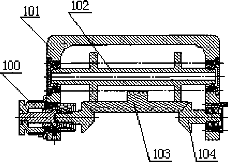
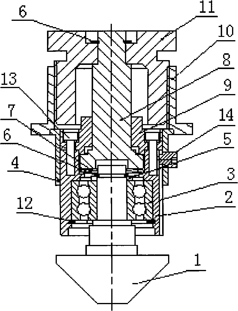
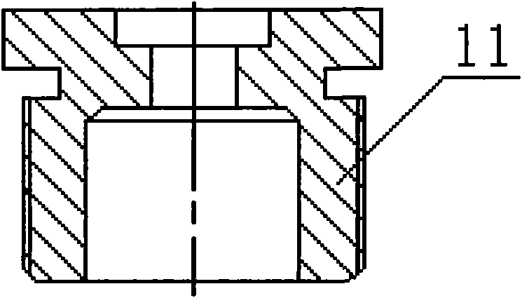
[0022] refer to figure 1 . The elastic positioning adjustment device of the cone wheel is mainly composed of the cone wheel shaft 1, the cone wheel shaft sleeve 2, the double row angular contact bearing 3, the copper sleeve 4, the bearing inner ring stop pad 5, the shaft circlip 6, the disc spring 7, and the floating shaft 8 , Bushing gland 9, adjusting mounting seat 10, adjusting hand wheel 11, circlip 12 for hole, fastening screw 13 and limit screw 14 are composed.

[0023] refer to Figure 9 . The cone shaft 1 is a stepped shaft whose lower end is a frustum, and the slope of the cone shaft 1 is 45 degrees. There is a retaining ring groove for the shaft at the upper end of the cone wheel shaft 1 . refer to figure 2 . A double-row angular contact bearing 3 is fixe...


PUM


Abstract

The invention discloses an elastic positioning adjusting device for a conical pulley, which is applied to the technical field of automatic welding. The elastic positioning adjusting device is characterized by consisting of a conical pulley shaft, a conical pulley shaft sleeve, a double row angular contact bearing, a copper bush, a bearing cone cushion, an elastic retainer ring for shafts, a disc spring, a movable shaft, a shaft sleeve gland, an adjusting mounting base, a regulating hand wheel, an elastic retainer ring for holes, fastening screws and limit screws. The elastic positioning adjusting device has the advantage that: the elastic positioning adjusting device realizes that the conical pulley can reliably and stably rotate, has functions of accurate elastic positioning and wide-range position adjustment, has looseness-proof function, has compact and even structure, meets the design requirements for miniaturization and portability of a welding carriage and a track, and improves the positioning precision and walking reliability of the steel pipe automatic welding carriage.

Description

technical field [0001] The invention relates to the technical field of automatic welding equipment, in particular to a welding trolley for an automatic welding machine, and is a positioning adjustment device for a welding trolley for an automatic welding machine. Background technique [0002] During the steel pipe welding construction, the welding trolley of the automatic welding machine walks along the circular track fixed on the steel pipe to realize the automatic welding of the pipe. The welding trolley of existing steel pipe automatic welding machine has 4 grooved wheels, and 4 grooved wheels are stuck on the circular track that steel strip bends into. Among the 4 sheaves, 2 are fixed runners with elastic positioning, and 2 are adjustable runners with rigid positioning. The existing welding trolley has relatively low positioning accuracy and cannot meet the requirements of automatic tracking steel pipe welding, and the existing structure of rigid positioning adjusting w...

Claims


Application Information

Patent Timeline
Patent Type & Authority Applications(China)
IPC IPC(8): B23K37/02
Inventor 张田利龙斌唐德渝李春润刘明珠牛虎理孙勃
Owner BC P INC CHINA NAT PETROLEUM CORP
Why Eureka
Try Eureka