Storage battery and insulating material and battery container using the same
A battery and electrode rod technology, which is applied in the field of battery containers for covers, can solve problems such as insufficient adhesion of insulating materials, and achieve good resistance and enhanced resistance
- Summary
- Abstract
- Description
- Claims
- Application Information
AI Technical Summary
Problems solved by technology
Method used
Image
Examples
Embodiment 1
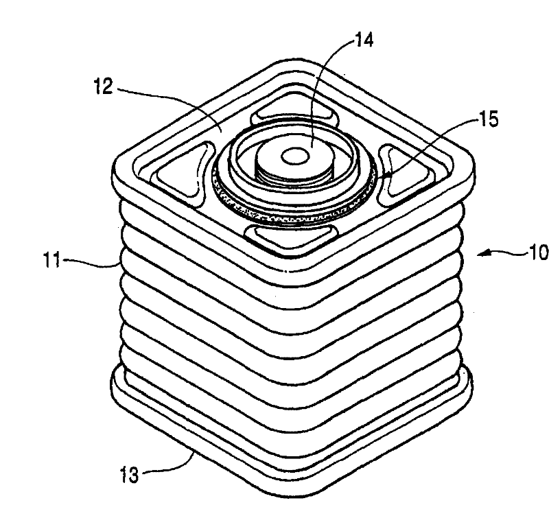
[0153] figure 1 is a perspective view of a battery according to the invention, a battery 10 is a sealed case comprising a corrugated (corrugated) barrel 11 , the upper opening of which is closed by a cover 12 and the lower opening of which is closed by a bottom cover 13 . The bottom cover 13 can be formed simultaneously with the barrel 11 by deep drawing. Reference numeral 14 denotes an electrode shaft, and reference numeral 15 denotes a ring.
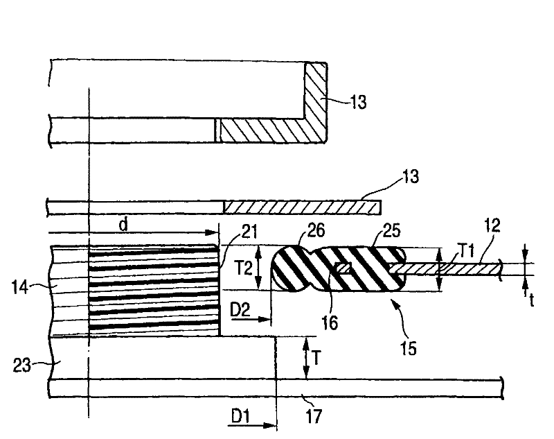
[0154] Explained below Figure 9 In the cover body 12 (30), the cover body 12 (30) has a hole 16 formed in its center, and a plurality of through holes 131 (37) are formed therein surrounding the hole 16. These through holes 131 ( 37 ) are formed to enhance the fixity of the ring member 15 .
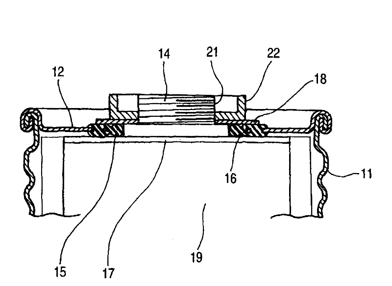
[0155] figure 2 is a sectional view of the main part of the storage battery according to the present invention, and shows a structure including a cover body 12 having a hole 16 formed therein, a ring member 15 arranged around the hole 16, a...
Embodiment 2
[0167] Another embodiment for carrying out the present invention will be described below.
[0168] Figure 5 is showing image 3 and includes a cover body 12 having a hole 16 formed therein, a ring member 15 disposed around the hole 16, arranged on one side of the cover body 12 (the lower side when viewed in the figure) The current collecting plate 17 on the top, the electrode rod 14 extending from the current collecting plate 17 and set to be able to extend out of the hole 16, and the pressing plate arranged on the other side (the upper side when viewed in the figure) of the cover body 12 18.
[0169] Also, the ring member 15 is formed of a resin sheet, and its front end is provided with a slope 28 for pressing against an O-ring 27 provided at the base of the electrode rod 14 .
[0170] In addition, the resin sheet is a hard resin having high strength but poor stretchability.
[0171] Image 6 is showing Figure 5 In the diagram of the function, the electrode rod 14 exte...
Embodiment 3
[0174] Figure 7 is showing image 3 and includes a cover body 12 having a hole 16 formed therein, a ring member 15 arranged around the hole 16, arranged on one side of the cover body 12 (the lower side when viewed in the figure) The current collecting plate 17 on the top, the electrode rod 14 extending from the current collecting plate 17 and set to be able to extend out of the hole 16, and the pressing plate arranged on the other side (the upper side when viewed in the figure) of the cover body 12 18.
[0175] Also, the ring 15 is formed of a resin sheet, and its front end is provided with a slope 28 for pressing against a paint 29 made of a composition including a PPT-based resin provided at the base of the electrode rod 14 .
[0176] In addition, the resin sheet is also a hard resin having high strength but poor stretchability, as in the foregoing embodiments.
[0177] Figure 8 is showing Figure 7 In the diagram of the function, the electrode rod 14 extends downward ...
PUM
| Property | Measurement | Unit |
|---|---|---|
| glass transition temperature | aaaaa | aaaaa |
| thickness | aaaaa | aaaaa |
| thickness | aaaaa | aaaaa |
Abstract
Description
Claims
Application Information
 - R&D
- Intellectual Property
- Life Sciences
- Materials
- Tech Scout
- Unparalleled Data Quality
- Higher Quality Content
- 60% Fewer Hallucinations
Browse by: Latest US Patents, China's latest patents, Technical Efficacy Thesaurus, Application Domain, Technology Topic, Popular Technical Reports.
© 2025 PatSnap. All rights reserved.Legal|Privacy policy|Modern Slavery Act Transparency Statement|Sitemap|About US| Contact US: help@patsnap.com


