Gain bootstrap type C class reverser and application circuit thereof
A technology of inverters and resistors, which is applied in the parts, electrical components, and generating electric pulses of electric pulse circuits. It can solve the problems of low gain, loss of function, and degradation of application circuit performance, so as to reduce circuit complexity and Effects of power consumption, increased circuit gain, and reduced chip footprint
- Summary
- Abstract
- Description
- Claims
- Application Information
AI Technical Summary
Problems solved by technology
Method used
Image
Examples
Embodiment 1
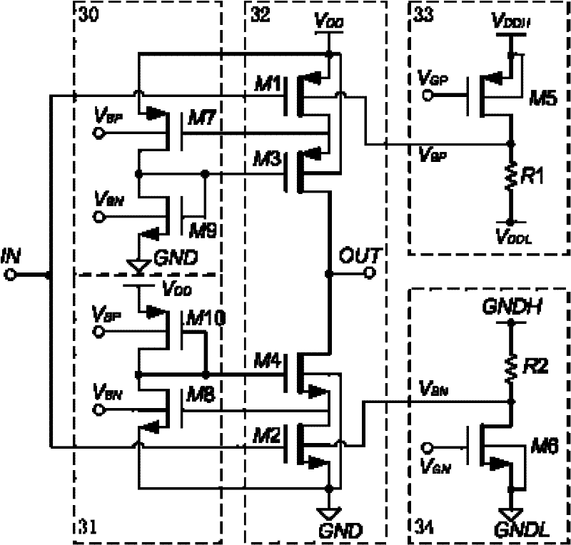
[0047] Embodiment 1: The circuit structure diagram of the gain bootstrap type C class inverter proposed by the present invention is as attached image 3 As shown, in addition to the class C inverter 32 , it also includes a first gain bootstrap module 30 , a second gain bootstrap module 31 , a PMOS body potential modulation module 33 and an NMOS body potential modulation module 34 .
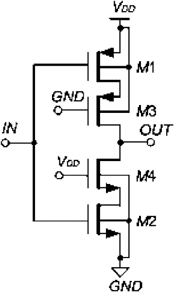
[0048] The class C inverter 32 is composed of a first PMOS transistor M1 , a second PMOS transistor M3 , a first NMOS transistor M2 and a second NMOS transistor M4 . The power supply voltage V of class C inverter 32 DD Slightly lower than the sum of the threshold voltage of the first PMOS transistor M1 and the first NMOS transistor M2, it can realize two different working states of high gain, low power consumption and high slew rate and high current according to the difference in the bias voltage of the input terminal. Detailed description as follows:
[0049] Assuming that the threshold voltag...
Embodiment 2
[0070] Embodiment 2: The pseudo-differential structure switched capacitor integrator proposed by the present invention is as attached Figure 4 As shown, it includes two gain bootstrap type C-type inverters 40 and a common-mode feedback circuit 41 of the prior art, a sampling capacitor C S , compensation capacitor C C , Integrating capacitance C I and switch. Among them, two gain-bootstrap class C inverters 40 are respectively located in the positive and negative branches of the integrator, and the two inverters are differentially symmetrical to form a pseudo-differential structure, while two common-mode feedback circuits 41 are respectively located in the integrator The positive and negative legs form a common-mode feedback.
[0071] In actual work, the switched capacitor integrator is divided into sampling phase and integrating phase, which are controlled by two non-overlapping clocks of p1 and p2, as shown in the attached Figure 5 As shown, the integral phase can be fu...
Embodiment 3
[0080] Embodiment 3: The 2-1 cascaded Sigma-Delta analog-to-digital converter proposed by the present invention includes a pseudo-differential switched capacitor integrator based on a gain-bootstrap class-C inverter. In order to illustrate the specific structure and working mode of the 2-1 cascaded Sigma-Delta analog-to-digital converter, let's start with the general structure and working mode of the Sigma-Delta analog-to-digital converter:
[0081] The structural block diagram of the Sigma-Delta analog-to-digital converter is attached Image 6 As shown, it includes an anti-aliasing filter 60 , a sample-and-hold 61 , an analog modulator 62 and a digital decimation filter 63 . The analog modulator 62 is used for noise shaping in the analog-to-digital conversion process, and it includes loop filter 65, feedforward ADC (analog-to-digital converter) 66, feedback DAC (digital-to-analog converter) 67, adder 64 and other parts, The feed-forward ADC66 and the feedback DAC67 are colle...
PUM
 Abstract
Description
Claims
Application Information
 - R&D
- Intellectual Property
- Life Sciences
- Materials
- Tech Scout
- Unparalleled Data Quality
- Higher Quality Content
- 60% Fewer Hallucinations
Browse by: Latest US Patents, China's latest patents, Technical Efficacy Thesaurus, Application Domain, Technology Topic, Popular Technical Reports.
© 2025 PatSnap. All rights reserved.Legal|Privacy policy|Modern Slavery Act Transparency Statement|Sitemap|About US| Contact US: help@patsnap.com


