
Method for encoding and decoding video, system and video monitoring system

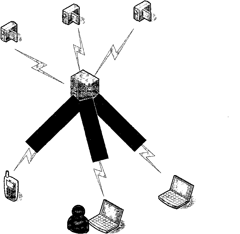
A video encoding and decoding and video decomposition technology, applied in the fields of video encoding and decoding methods, systems, and video monitoring systems, can solve the problem of poor stream processing and display capabilities, inability to adapt to various network environments and terminal equipment, and inability to achieve playback effects. and other problems to ensure continuity and real-time performance, improve video playback effects, and improve video surveillance effects.

Inactive Publication Date: 2010-04-07
ZTE CORP
View PDF0 Cites 7 Cited by
  • Summary
  • Abstract
  • Description
  • Claims
  • Application Information

AI Technical Summary

Problems solved by technology

For example, some clients access services through high-speed Ethernet, some clients access services through medium-speed modulators, and some users can only access services through low-speed wireless networks due to limited conditions. The access method leads to different network bandwidths. Even if the client uses the same access method, it may result in different network bandwidths at different times due to different network conditions. In the case of large fluctuations, it may cause video data loss or delay. For example, when decoding video, it usually decodes sequentially from the I frame. If any I frame is lost or damaged, it may affect the subsequent P frames. decoding
There are also some clients with poor device performance, poor bit stream processing and display capabilities, so when the client is playing video, there may be serious delays, blurred screens, mosaics and other practical problems that cannot achieve clear and smooth playback effects
Therefore, the existing video coding and decoding methods cannot adapt to various network environments and terminal equipment, and it is difficult to meet the actual needs of users.

Method used


Image

  • Method for encoding and decoding video, system and video monitoring system
  • Method for encoding and decoding video, system and video monitoring system
  • Method for encoding and decoding video, system and video monitoring system

Examples


Embodiment Construction

[0042] In the video decoding method of the present invention, after encoding and decoding continuous videos in groups, according to the network environment, equipment performance and other conditions, the code stream group containing only a part of the data frames in the original video is provided to the decoding end, and the decoding When the terminal decodes the data frames in the stream group, the P frame in each sub stream group only depends on the I frame or P frame in the group for decoding. The specific embodiments of the present invention will be further described below in conjunction with the accompanying drawings.

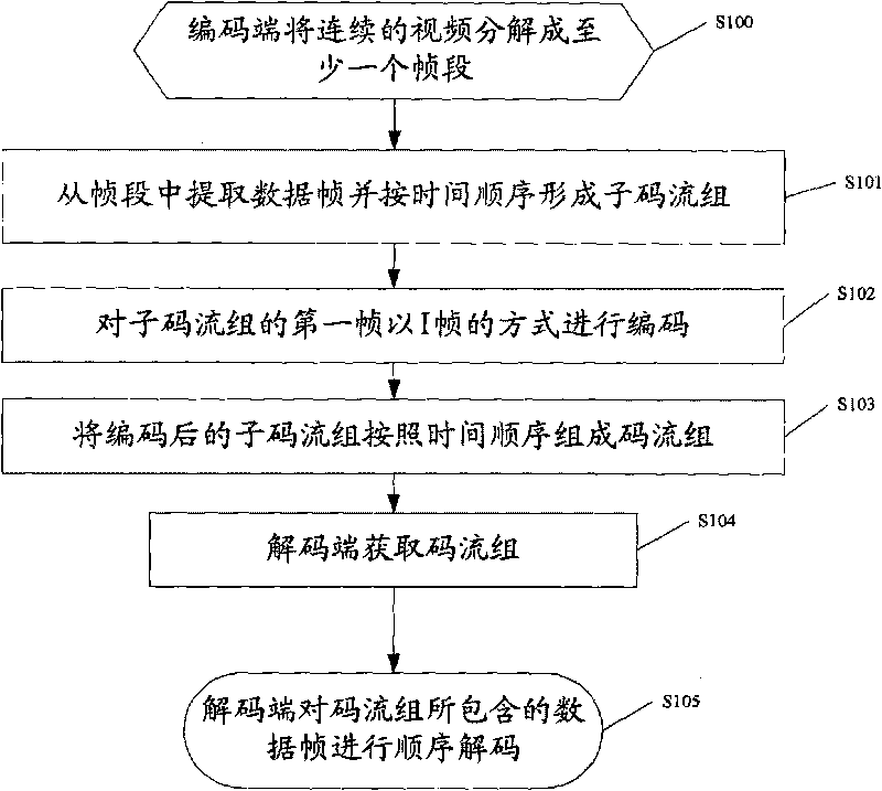
[0043] figure 1 It is a flow chart of a specific embodiment of the video encoding and decoding method of the present invention, including the following steps:

[0044]Step S100: The encoder decomposes the continuous video into at least one frame segment. The decomposition method and length of the frame segment can be determined according to specific need...


PUM


Abstract

The invention discloses a method for encoding and decoding a video, a system and a video monitoring system. The method comprises the following steps: decomposing a continuous video into at least one frame segment by an encoding end, and extracting data frames from the frame segment to form a sub-code stream group according to a time sequence; encoding a first frame of the sub-code stream group in an I-frame mode; forming a code stream group by using the encoded sub-code stream group according to the time sequence; and acquiring the code stream group by an decoding end, and sequentially decoding the data frames contained in the code stream group. The method for encoding and decoding the video, the system and the video monitoring system are suitable for various network environments and equipment characteristics, and significantly improve the video playing effect.

Description

technical field [0001] The present invention relates to the field of multimedia technologies, in particular to a video encoding and decoding method, system and video monitoring system. Background technique [0002] The encoding method of video usually includes I frame, P frame and B frame. Among them, I frame is a self-reference frame (also called intra-frame coding frame), that is, the coding of I frame does not refer to other data frames. Correspondingly, it can not rely on The data of other frames can be independently decoded; the P frame is a one-way reference frame, that is, the encoding of the P frame needs to refer to the previous frame or frames in the sequence, and accordingly, it needs to rely on the decoding data of the previous frame or frames Decoding; the B frame is a bidirectional reference frame, that is, the encoding of the B frame needs to refer to the previous and subsequent data frames of the time sequence, and accordingly, it needs to rely on the previou...

Claims


Application Information

Patent Timeline
IPC IPC(8): H04N7/32H04N7/18
CPCH04N19/00781H04N19/00884H04N7/26946H04N19/00266H04N7/26271H04N7/50H04N19/172H04N19/61H04N19/70
Inventor 张莉
Owner ZTE CORP
Learn More