Automobile muffler for reducing exhaust back pressure

A technology of automobile muffler and exhaust back pressure, which is applied in the direction of mufflers, machines/engines, engine components, etc., can solve the problems of torque drop, increase of air flow velocity, increase of exhaust air flow velocity and exhaust back pressure, etc., to achieve reduction The effect of velocity

Inactive Publication Date: 2010-04-14
CHONGQING CHANGAN AUTOMOBILE CO LTD
View PDF0 Cites 8 Cited by
  • Summary
  • Abstract
  • Description
  • Claims
  • Application Information

AI Technical Summary

Problems solved by technology

[0003] In the automobile muffler of the above-mentioned prior art structure, since the inlet pipe, the outlet pipe and the transition pipe body are all straight pipes, the exhaust air flow enters from the inlet pipe, passes through the transition pipe, and is discharged from the outlet pipe, and the gas is suddenly expanded. , Compression, expansion, and recompression, resulting in an increase in airflow velocity, an increase in exhaust airflow velocity leads to an increase in exhaust back pressure, and a decrease in engine power and torque

Method used


Image

  • Automobile muffler for reducing exhaust back pressure
  • Automobile muffler for reducing exhaust back pressure

Examples


Embodiment Construction

[0014] Below in conjunction with accompanying drawing and specific embodiment the present invention is described in further detail:

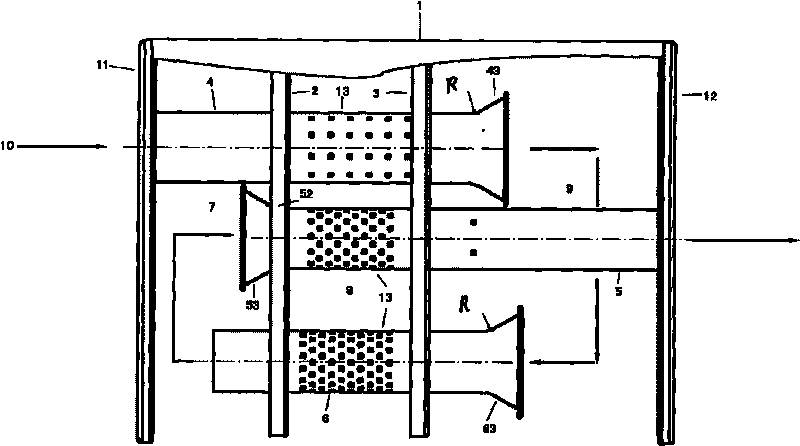
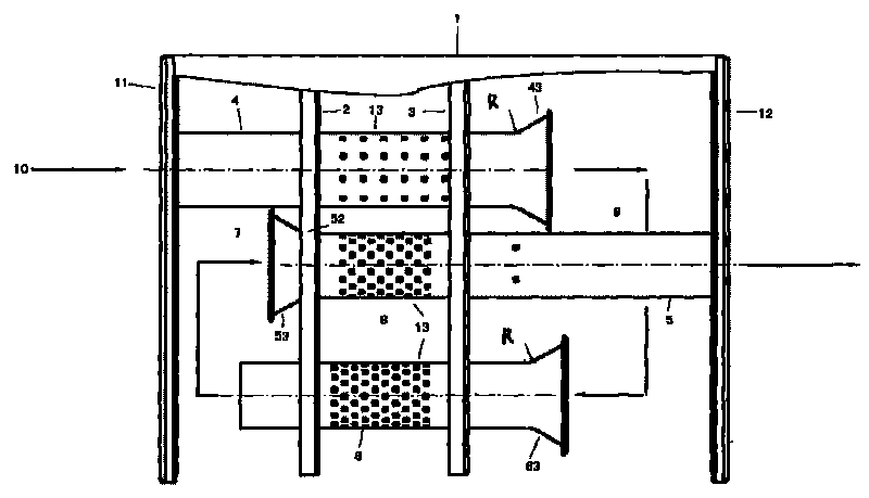
[0015] see figure 1 , the housing 1 of the automobile muffler of the present invention is provided with a first baffle 2 and a second baffle 3 vertically in the axial direction, arranged at intervals to isolate the inside of the housing 1 into a first expansion chamber 7, a resistive muffler chamber 8 and the second expansion chamber 9 are three chambers. The air inlet pipe 4 , the air outlet pipe 5 and the transition pipe 6 are axially parallel to the housing 1 and arranged at intervals in the housing. The air inlet pipe 4 passes through the front end cover 11 of the housing 1 and the first partition plate 2 and the second partition plate 3 from the outside of the housing 1 and then penetrates into the second expansion chamber 9; the air outlet pipe 5 passes through the first expansion chamber 7 After passing through the first partition 2, th...


PUM


Abstract

The invention provides an automobile muffler for reducing exhaust back pressure. For the muffler, a shell is internally provided with a first baffle plate and a second baffle plate which divide the inner part of the shell into three chambers sequentially, including a first and a second expanding chamber and a resistive muffling chamber; from outside the shell, an air inlet pipe sequentially passes through a front end cover of the shell, the first baffle plate and the second baffle plate and then extends into the second expanding chamber; from the first expanding chamber, an air outlet pipe sequentially passes through the first baffle plate, the second baffle plate and the rear end cover of the shell and then passes out of the shell; a transition pipe passes through the first baffle plate and the second baffle plate from the first expanding chamber and then extends into the second expanding chamber; inside the resistive muffling chamber, parts of the air inlet pipe, the air outlet pipe and the transition pipe are all provided with micropores on pipe walls; and the outlet end of the air inlet pipe, the inlet end of the air outlet pipe and the inlet end of the transition pipe are all of the structure of expanded openings. The structure of the muffler can reduce the speed of exhaust air stream through smooth expansion and contraction, and expansion and contraction again, decrease the exhaust back pressure and improve the power and torque of a motor.

Description

technical field [0001] The invention relates to automobile noise reduction technology, in particular to an automobile muffler. Background technique [0002] At present, the structure of the automobile muffler used on the automobile is as follows: in the closed casing, the first and second partitions are arranged perpendicular to the axial direction of the casing and spaced from each other, and isolate the inside of the casing into first and second expansion plates. Chamber and resistive anechoic chamber Three chambers. The air inlet pipe, the air outlet pipe and the transition pipe are parallel to the axial direction of the housing and arranged at intervals. The air intake pipe passes through the front end cover of the housing and the first and second partitions sequentially from the outside of the housing, and then enters the second expansion chamber. The air outlet pipe passes through the first and second partitions and the rear end cover sequentially from the left chamb...

Claims


Application Information

Patent Timeline
Patent Type & Authority Applications(China)
IPC IPC(8): F01N1/08F01N7/08
Inventor 叶天行瞿尚胜戴永蓥李倩倩
Owner CHONGQING CHANGAN AUTOMOBILE CO LTD
Why Eureka
Try Eureka