Electrothermal speed controller of silicon oil fan

A speed control controller, electronic controller technology, applied in the direction of coolant flow control, clutch, fluid clutch, etc., can solve the problems that cannot be widely used, and the fixing method is difficult, etc., to achieve less moving parts, high reliability, The effect of fewer parts

Inactive Publication Date: 2010-04-14
苏新页
View PDF0 Cites 8 Cited by
  • Summary
  • Abstract
  • Description
  • Claims
  • Application Information

AI Technical Summary

Problems solved by technology

Because the fixed method is difficult in pra

Method used


Image

  • Electrothermal speed controller of silicon oil fan
  • Electrothermal speed controller of silicon oil fan
  • Electrothermal speed controller of silicon oil fan

Examples


Embodiment 1

[0040] Example 1: see Figure 8 , The electric fan 1 is installed in front of the intercooler A and blows backward. An air duct 4 is coaxially installed behind the intercooler A, which overlaps with another air duct 4 installed in front of the cooler B. The electric heater 2 is installed coaxially with the air duct 4, and all axes are consistent with the center of the silicon oil fan clutch C. There is a wind mask 5 at the rear of the electric heater 2 to concentrate the hot air and adjust the gap. After the electric fan 1 is started, the blown air is heated by the intercooler A and the cooler B, and then is compensated by the electric heater 2 according to the control strategy and then blown to the bimetallic temperature sensor D of the silicon oil fan clutch C. After the electric heater 2 is used, the temperature of intercooler A and cooler B is no longer completely dependent, and the fan speed hysteresis effect caused by the temperature sensor is overcome, and the silicone ...

Embodiment 2

[0041] Example 2: see Picture 9 , The electric fan 1 is combined with the electric heater 2 and the air mask 5 to form a hot air blower, which is installed on the bracket E connected to the cooler behind the cooler B, and enters the electric fan 1 through the intercooler A (not shown) ), the air heated by the cooler B is further heated by the electric heater 2 and then blown to the bimetallic temperature sensor D of the silicon oil fan clutch C. After electric heater 2 is used, the temperature of intercooler A and cooler B is no longer completely dependent, and the hysteresis effect of fan speed is overcome, and the silicon oil fan clutch C can be intelligently controlled according to the temperature change rate, so that the coolant temperature is kept in the ideal range , To achieve the purpose of energy saving and emission reduction.

Embodiment 3

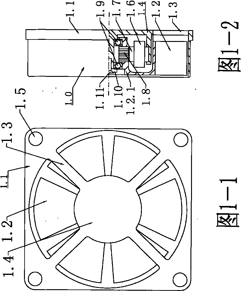
[0042] Example 3: See Picture 10 ,will image 3 The shown integrated hot air blower (the casing 1-2) is installed on the bracket E connected to the cooler behind the cooler B, and the hot air is blown to the bimetallic temperature sensor D of the silicone oil fan clutch C through the air mask 5.


PUM


Abstract

An electrothermal speed controller of a silicon oil fan comprises an electronic controller, an electric fan, an electric heater, an air duct, an air outlet, an inter-cooling air-intake temperature sensor and a coolant liquid temperature sensor. The electronic controller, the electric fan, the electric heater, the air duct and the air outlet are mounted sequentially, the air outlet corresponds to a bimetallic temperature sensor of a silicon oil fan clutch, and the electric fan and the electric heater are connected with the electronic controller. The electrothermal speed controller is characterized in that a rotation speed sensor is arranged on the electric fan, the electric heater is arranged in an air outlet direction of the electric fan, a temperature sensor is arranged on the electric heater, and the electric fan, the rotation speed sensor, the electric heater and each temperature sensor are connected with a driving power supply via the electronic controller. On a condition of keeping the structure of the existing silicon oil fan clutch completely, the electrothermal speed controller is added with parts such as the electric fan, the electric heater, the coolant liquid temperature sensor, the air-intake temperature sensor, the electronic controller, an air port cover and the like, thereby realizing control to rotation speed of the fan according to temperature of a motor and having functions of saving energy and reducing emission.

Description

Technical field [0001] The invention relates to an electric heating type silicone oil fan speed regulating controller used for engine heat dissipation control, in particular to an electric heating type silicone oil fan speed regulating controller which uses a temperature value to transmit information and control a silicone oil fan clutch. The electric heating type silicon oil fan speed control controller of the present invention includes an electric fan, an electric heater, a temperature sensor, an electronic controller, a wind cover and the like. Background technique [0002] According to the published literature, the engine cooling fan consumes 5-10% of the engine's power, and most of the time is ineffective or excessively running. In order to keep the engine working within the required temperature range and save energy, it is necessary to control the fan speed. To this end, people designed silicon oil clutch fans, hydraulic drive fans, electric fans, electromagnetic clutch fa...

Claims


Application Information

Patent Timeline
IPC IPC(8): F01P7/04F16D35/00
Inventor 苏新页
Owner 苏新页
Why Eureka
Try Eureka