Coal and gas separation bin and method thereof

A technology for separating bins and gas, which is applied in the direction of gas discharge, earthwork drilling, safety devices, etc., and can solve the problems of life of underground operators, damage of well lanes and electromechanical equipment, uncontrollable and separation of outburst jet flow coal and gas, expansion Disaster scope and other issues, to achieve the effect of increasing coal and gas output in drilling outbursts, wide application, and avoiding damage

Inactive Publication Date: 2010-04-21
CHINA UNIV OF MINING & TECH
View PDF0 Cites 4 Cited by
  • Summary
  • Abstract
  • Description
  • Claims
  • Application Information

AI Technical Summary

Problems solved by technology

The outburst is accompanied by strong coal destruction, coal and gas ejection, and the formation of outburst holes and a certain range of pressure relief. In the past, the coal and gas that occurred in large and medium-sized coal and gas outbursts were naturally discharged through the roadway, which is harmful to underground workers. Life, wells, and mechanical and electrical equipment will be destroyed, and even gas explosions will occur, which will expand the scope of the disaster and cause heavy casualties and property losses.
The intensity of coal and gas outburst induced by hydraulic punching is small, and coal, water, and gas are generally separated by small separators, which cannot control and separate a large number of outburst jets of coal and gas

Method used


Image

  • Coal and gas separation bin and method thereof
  • Coal and gas separation bin and method thereof

Examples


Embodiment Construction

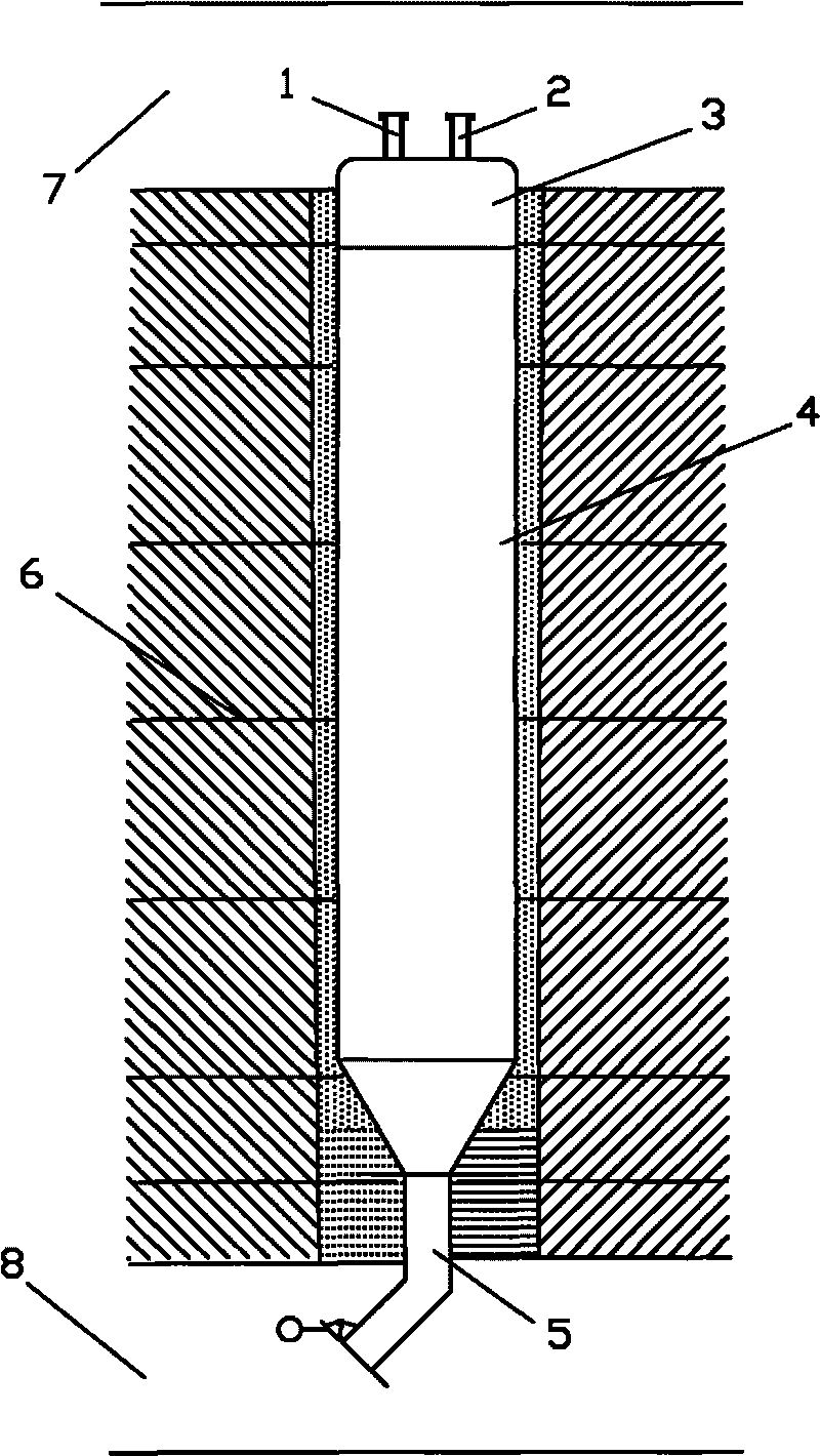
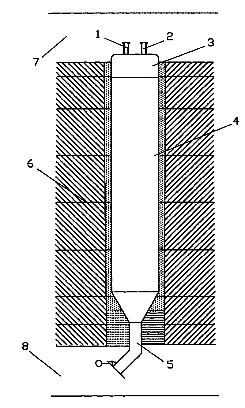
[0017] Embodiments of the present invention will be further described below in conjunction with the accompanying drawings:

[0018] As shown in Figure 1, between the upper roadway 7 and the lower roadway 8, the lower part is poured into a funnel-shaped concrete separation bin body 4, and the bottom of the concrete separation bin body 4 is poured with a separation bin coal discharge pipe 5, and the separation bin coal discharge pipe 5 The coal outlet is provided with a counterweight door; the upper part of the concrete separation chamber body 4 is poured with a separation chamber cover 3, and the top of the separation chamber cover 3 is respectively provided with a jet pipe joint 1 and a discharge pipe joint 2 connected with the discharge pipe; The concrete separation bin body 4 is formed by pouring concrete, and its inner diameter is greater than 2 meters. The separation bin cover 3 and the separation bin coal discharge pipe 5 respectively arranged on the top and bottom of the ...


PUM


Abstract

The invention relates to a coal and gas separation bin and a method thereof. The separation bin is integrally poured with concrete reinforced by anchor rods; the bottom of the separation bin is funnel-shaped; the lower part of the separation bin is a coal discharge pipe, and the upper part of the separation bin is a cover; the top part of the cover of the separation bin is provided with a jet pipe flanged joint and a drawing pipe flanged joint; and a coal discharge opening of the coal discharge pipe of the separation bin is provided with a counterbalance type bin gate. Jet materials protruding out of an excitation borehole are introduced into the separation bin, the drawing pipe is used for drawing gas so that the interior of the separation bin is in a negative pressure state to weaken the jet flow impact and achieve the separation of the coal and the gas; the coal entering the separation bin automatically opens the coal discharge opening of the separation bin and flows out under the action of gravity, and then the coal is carried away by a transporter on a lower laneway; and when the coal in the bin is emptied, under the action of a counterbalance at the coal discharge opening, the coal discharge opening is closed automatically so that the interior of the bin is kept in the negative pressure state. The jet materials with repeated coal and gas protrusions on a coal layer in the excitation borehole are separated to achieve that tens of thousands of coals are mined through a single hole. The coal and gas separation bin has a simple structure, simple and convenient method, and has easy construction and good effect.

Description

technical field [0001] The present invention relates to a technology of stimulating drilling outburst coal mining and gas extraction, especially a coal and gas separation bin and method suitable for drilling jet flow in low permeability, low strength and high gas coal seams and gas outburst coal seams . Background technique [0002] Coal and gas outburst is a major disaster in underground coal mine production. The outburst is accompanied by strong coal destruction, coal and gas ejection, and the formation of outburst holes and a certain range of pressure relief. In the past, the coal and gas that occurred in large and medium-sized coal and gas outbursts were naturally discharged through the roadway, which is harmful to underground workers. Life, wells, and mechanical and electrical equipment will be destroyed, and even gas explosions will occur, which will expand the scope of the disaster and cause heavy casualties and property losses. The intensity of coal and gas outburs...

Claims


Application Information

Patent Timeline
Patent Type & Authority Applications(China)
IPC IPC(8): E21F7/00
Inventor 罗新荣罗玉霖
Owner CHINA UNIV OF MINING & TECH
Why Eureka
Try Eureka