
Mining automatic signal blocking system for transportation region and control method

A technology of automatic blocking and blocking signals, applied in mining equipment, mining equipment, earthwork drilling and mining, etc., can solve problems such as difficult maintenance, high maintenance cost, and many scheduling operations, and achieve the effect of ensuring safe operation

Inactive Publication Date: 2012-05-23
CHINA UNIV OF MINING & TECH
View PDF4 Cites 0 Cited by
  • Summary
  • Abstract
  • Description
  • Claims
  • Application Information

AI Technical Summary

Problems solved by technology

[0002] At present, mine locomotive transportation management adopts a large railway signal, centralized, and blocked dispatching method. This method has the following problems: 1) There are too many dispatching operations such as manual delivery of the system, which is not conducive to reducing personnel and improving efficiency; 2) There are too many sensors in the system , resulting in high maintenance costs and poor reliability after application
cumbersome operation
4) The system cannot run normally and reliably for a long time, the failure rate is high, and maintenance is difficult
In order to prevent and stop vehicle accidents on the above-mentioned road sections, standardize the management of locomotive running signals, and strictly enforce the operating procedures for drivers to read signals, this kind of monitoring system has no precedent at home and abroad.

Method used


Image

  • Mining automatic signal blocking system for transportation region and control method
  • Mining automatic signal blocking system for transportation region and control method
  • Mining automatic signal blocking system for transportation region and control method

Examples


Embodiment Construction

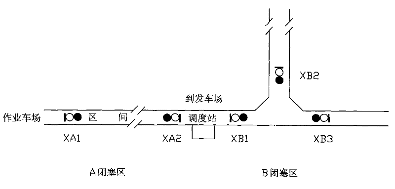
[0026] figure 1 Shown is a typical mining area operation yard. The yard is divided into A block area and B block area. There is a dispatching station from the operation yard to the departure yard (between the two block areas). Among them: A block area is a one-way traffic block There are two blocking signals XA1 and XA2 respectively at the entrances of the two ends of the blocking area; the B blocking area is the one-way traffic blocking area of ​​the three-way intersection, and three blocking signals XB1, XB1, XB2, XB3. In the same way, if there are multiple forks in the one-way traffic blocking area, multiple blocking signals are set at the entrances of the multiple forks.

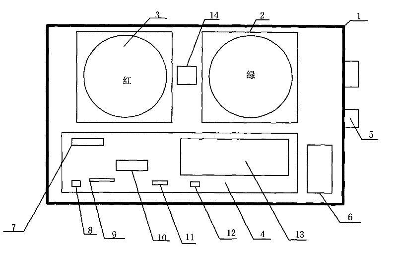
[0027] figure 2 Shown is a block diagram of the block signal machine, which is mainly composed of a box 1, a light-emitting tube plate 2, a light-transmitting lampshade 3, a program-controlled circuit 4, a light-emitting tube driver 7, an external signal 8, a block control line 9, an optocoupler 10, a...


PUM


Abstract

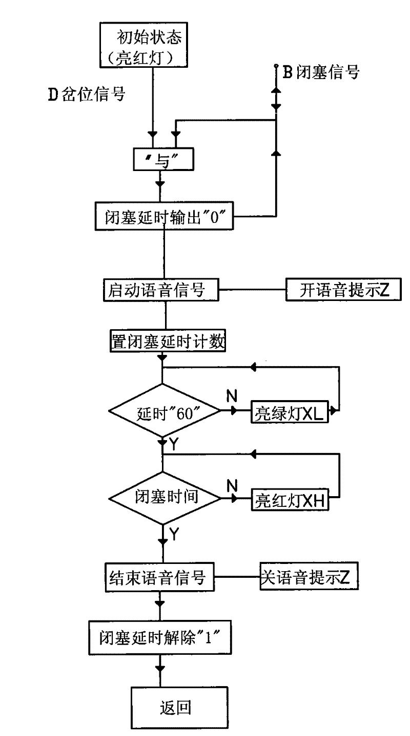
The invention relates to a mining automatic signal blocking system for a transportation region and a control method. The system comprises two sets of mutually controlled signal blocking machines respectively arranged on entrances on both ends of a one-way block section or a plurality of mutually controlled signal blocking machines respectively arranged on entrances of one-way block sections of a plurality of crossways, and signal lights indicating the initial states of the signal blocking machines are respectively red; and when needing to enter the block region, a vehicle applies for a crossway signal, block signal lights are switched to be green periodically by a program-controlled circuit, the light of a conflicting signal locking machine is always red, the vehicle enters the block region, a voice prompt is stopped until the vehicle safely passes through the block region, and the signal blocking machines return to the initial states and wait for the application of the crossway signal in the next round. The passive scheduling mode of blind calling in the past is changed by the system, a sensor does not need to be installed, field signals do not need the participation of artificial scheduling, the system is reliable, the independence performance of automatic signal blocking is strong, and accidents of vehicle clash, side crash, pileup, and the like can be effectively avoided during transportation.

Description

technical field [0001] The invention relates to an automatic blocking signal system of a transportation section, in particular to an automatic blocking signal system suitable for the safety of transport vehicles in mines, mines and roadways. Background technique [0002] At present, mine locomotive transportation management adopts a large railway signal, centralized, and blocked dispatching method. This method has the following problems: 1) There are too many dispatching operations such as manual delivery of the system, which is not conducive to reducing personnel and improving efficiency; 2) There are too many sensors in the system , resulting in high maintenance costs and poor reliability after application. 3) The signal occlusion of the approach or interval signals all rely on manual operation. The operation is cumbersome. 4) The system cannot operate normally and reliably for a long time, with a high failure rate and difficult maintenance. According to mine conditions...

Claims


Application Information

Patent Timeline
Patent Type & Authority Patents(China)
IPC IPC(8): E21F17/18
Inventor 李玉良李晶刘广军贺新民
Owner CHINA UNIV OF MINING & TECH
Learn More