
Lighting protection system

Active Publication Date: 2017-12-14
SIEMENS GAMESA RENEWABLE ENERGY AS
View PDF5 Cites 10 Cited by
  • Summary
  • Abstract
  • Description
  • Claims
  • Application Information

AI Technical Summary

Benefits of technology

The invention provides a wind turbine with a lightning protection system that reduces the likelihood of discharge sparks. This is achieved by continuously providing a discharge path to ground for any static charge that might otherwise accumulate on the blade lightning conductors. The wind turbine can also comply with EMC regulations even when atmospheric conditions would favor the build-up of static charge. Additionally, the hub of the wind turbine is grounded by a conductor that runs along its rotational axis, which prevents static charge from accumulating on the hub. The hub also has a sealed rotary joint that ensures its primary function as an electrical conductor will not be compromised by any thin film accumulation. A sliding brush bracket is used to securely mount a sliding brush to the down conductor, which ensures that lightning current passes through the sliding brush to ground safely. Overall, the invention provides a wind turbine that can withstand lightning strikes and maintain electrical safety.

Problems solved by technology

The blades of a wind turbine are particularly vulnerable to lightning strikes on account of their length.
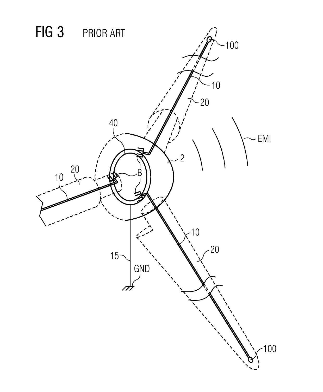
A problem with this kind of lightning protection system arises on account of the nature of the electrical system defined by the moving and stationary lighting conductors, the interface between them, the outside environment, and the environment inside the hub.
However, the environment inside the hub is not ideal, since contamination in the form of oil, grease and / or particles detracts from the function of the sliding brushes.
Even if such components are well sealed, it is basically unavoidable that some quantity of grease or oil will escape over the course of time.
The LPS of the wind turbine therefore unintentionally acts as a source of electromagnetic noise.
The level of electromagnetic noise can reach levels that compromise adherence to electromagnetic compatibility (EMC) limits laid down by various standards.

Method used


Image

  • Lighting protection system
  • Lighting protection system
  • Lighting protection system

Examples


Embodiment Construction

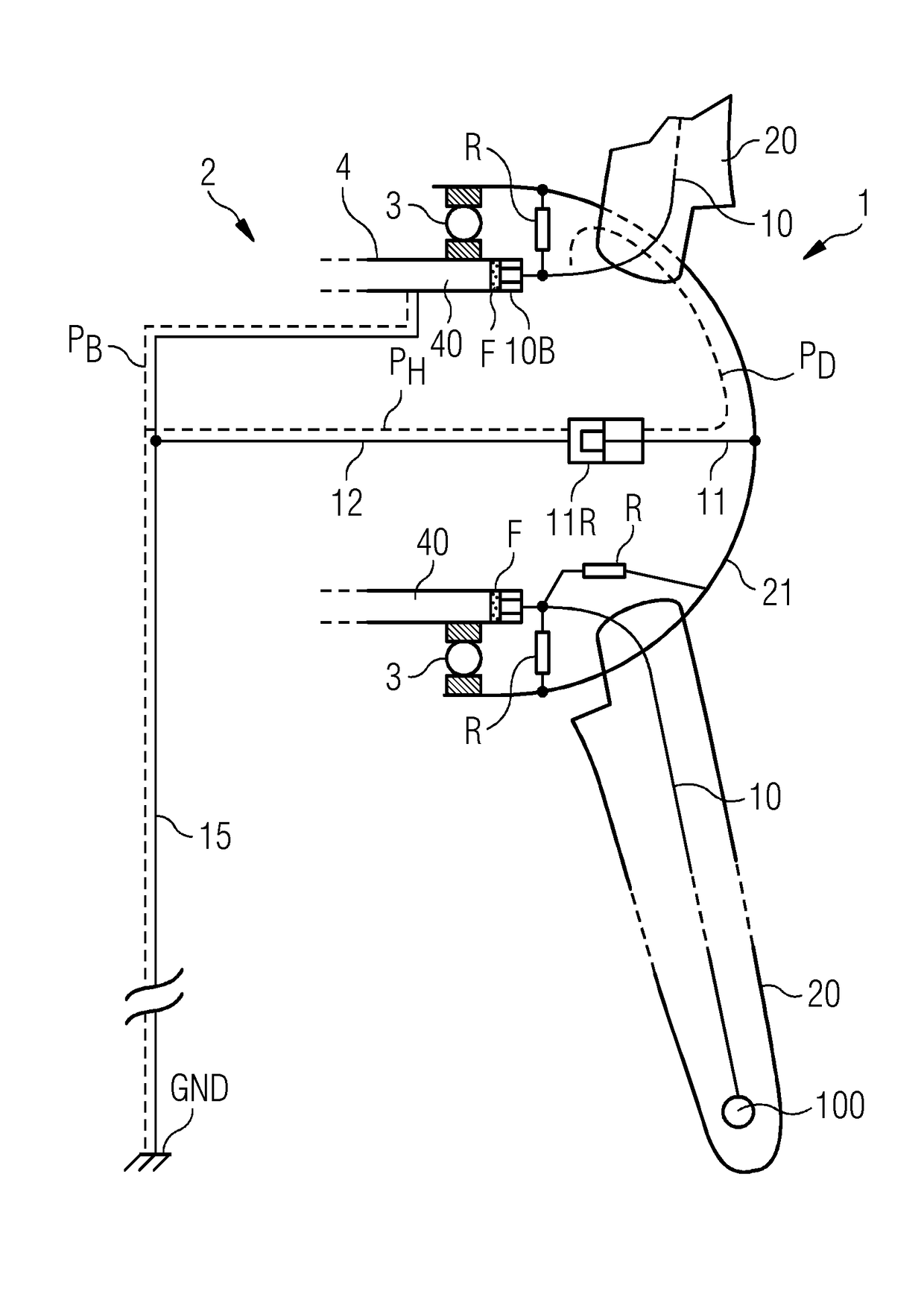
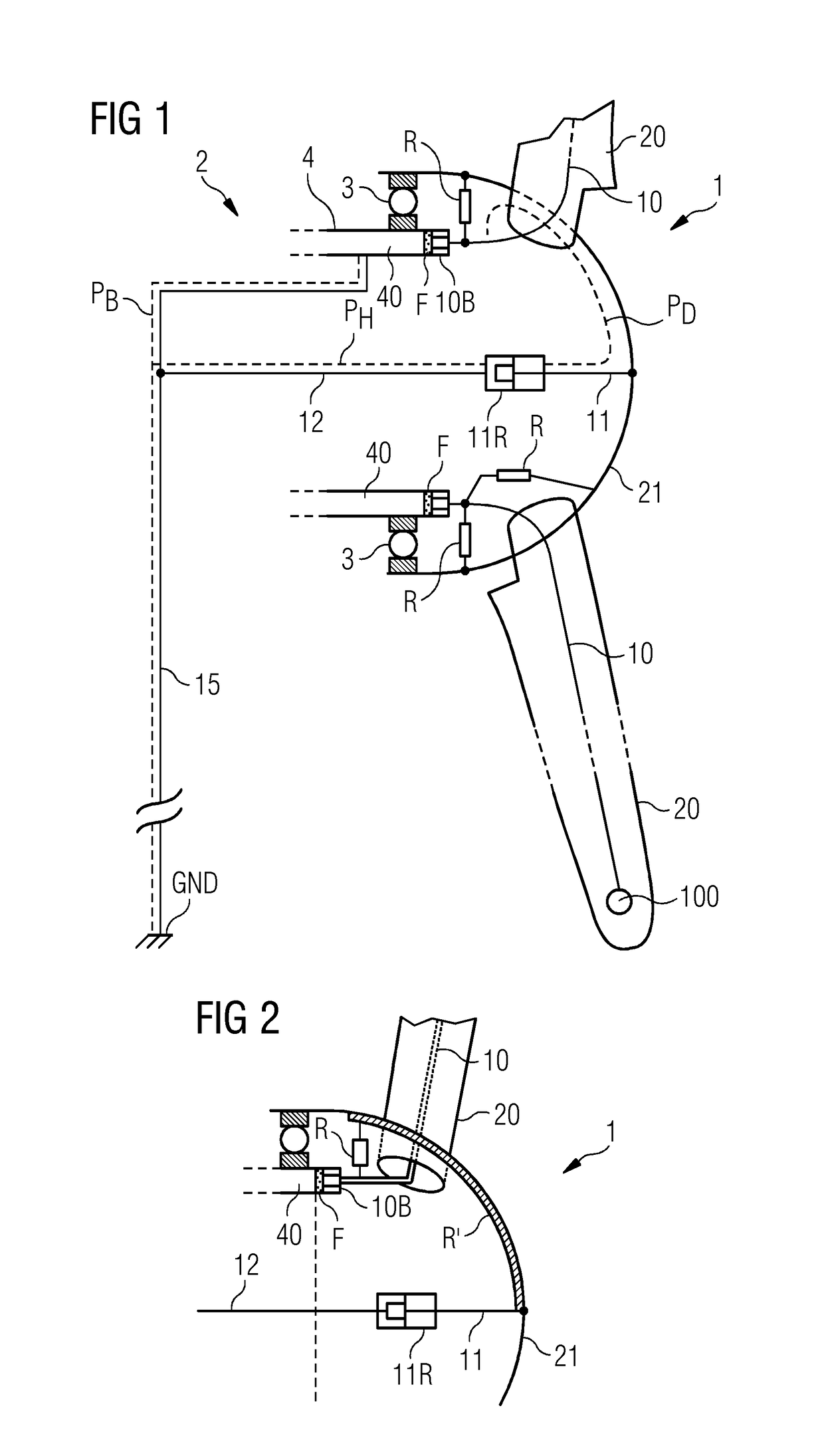
[0026]FIG. 1 shows a lightning protection system 1 according to embodiments of the invention. The diagram is a very simplified schematic representation showing only the relevant aspects of the inventive LPS 1 installed in a wind turbine. A wind turbine hub 21 is indicated. The hub 21 is mounted to a nacelle 4 of the wind turbine by means of a bearing 3. The hub 21, which can also be hit by a lightning strike, is provided with a hub lightning conductor 11. Since the hub 21 rotates relative to the nacelle, a sealed rotary joint 11R connects the rotating hub lightning conductor 11 to a stationary conductor 12, which in turn leads to ground GND. Several blades 20 are mounted to the hub 21. A lightning conductor 10 extends along the length of each blade 20, terminating at the outer blade end in a receptor 100 which ensures that a lightning strike is received in a controlled manner. The other ends of each lightning conductor 10 terminate at a brush 10B, which is in contact with a stationa...


PUM


Abstract

A lightning protection system of a wind turbine is provided, including a blade lightning conductor arranged in a rotor blade of the wind turbine to extend into the hub, a stationary conductor to provide a blade grounding path to ground during a lighting strike, a brush arranged to electrically connect the blade lightning conductor and the stationary conductor, and a discharge means arranged to provide a separate discharge path from the blade lightning conductor to ground. Furthermore, a wind turbine, and a method of equipping a wind turbine with a lightning protection system, is also provided.

Description

CROSS-REFERENCE TO RELATED APPLICATIONS[0001]This application claims priority to European application No. EP 16173684.8 having a filing date of Jun. 9, 2016, the entire contents of which are hereby incorporated by reference.FIELD OF TECHNOLOGY[0002]The following relates to a lighting protection system of a wind turbine, and a wind turbine comprising such a lightning protection system.BACKGROUND[0003]A tall structure such as a wind turbine is equipped with a lightning protection system (LPS) which serves to receive a stroke at one or more specific sites or receptors, and to divert the ensuing electrical current to ground during a lightning strike. The blades of a wind turbine are particularly vulnerable to lightning strikes on account of their length. The LPS of a wind turbine therefore generally includes a lightning conductor for each blade, arranged in the interior of the blade and extending along its length from base to tip. The blades are generally mounted to a hub or spinner, an...

Claims


Application Information

Patent Timeline
IPC IPC(8): F03D80/30H02G13/00
CPCF03D80/30F05B2240/14H02G13/40H02G13/80F05B2230/80Y02E10/72Y02P70/50
Inventor NIEUWENHUIZEN, JOHN
Owner SIEMENS GAMESA RENEWABLE ENERGY AS
Learn More