Bi-component valve

A two-component, valve body technology, applied to valve details, multi-way valves, valve devices, etc., can solve the problems of easy wear of the sealing ring pad, slow dispensing speed, inconvenience, etc., and achieve a sealing structure that is not easy to damage and has high performance. Diversified, clean glue breaking effect

Active Publication Date: 2010-04-21
SHENZHEN AXXON AUTOMATION
View PDF4 Cites 10 Cited by
  • Summary
  • Abstract
  • Description
  • Claims
  • Application Information

AI Technical Summary

Problems solved by technology

In the process of assembling the components back to the two-component valve after cleaning or replacing the components, the piston spring will produce a reverse force during the assembly process, often resulting in the need for two people to install the two-component valve. The situation where the valve assembly is compl

Method used


Image

  • Bi-component valve
  • Bi-component valve
  • Bi-component valve

Examples


Embodiment 1

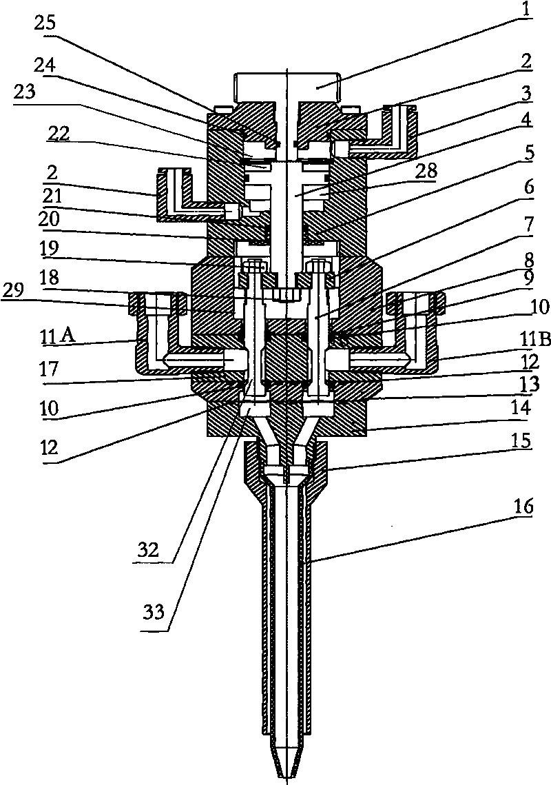
[0028] Such as figure 1 as shown,

[0029] A two-component valve, a valve body includes an upper valve body 5 and a lower valve body 18, the head of the upper valve body 5 is provided with an adjustment knob 1, and a cylinder 28, the A cavity 29 is set in the middle of the lower valve body 18, a first channel 20 is set between the cylinder 22 and the cavity 29, and at least one glue outlet hole is set at the bottom of the lower valve body 18, and the glue outlet hole and the The cavity 29 is connected; as required, one, two, three or even more glue outlet holes can be set. In this embodiment, two glue outlet holes are provided, namely the first glue outlet hole 33 and the The second glue hole.

[0030] A first piston 4, the head of the first piston 4 is a cross-shaped head, the cross-shaped head is arranged in the cylinder 22, and the cross-shaped head is connected with the adjusting knob 1 , the middle part of the first piston 4 is set in the first channel 20, the tail of ...

Embodiment 2

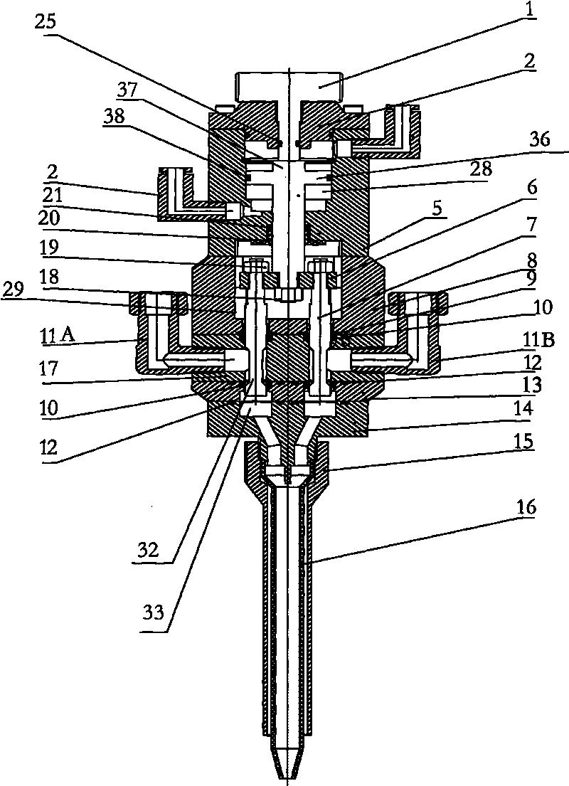
[0039] Such as figure 1, figure 2 as shown,

[0040] In the process of daily use, the two-component valve is usually installed on the fixed end of the glue dispensing machine or manipulator or robot to complete the glue spraying process. First, adjust the head adjustment knob 1 set on the upper valve body 5 to make the upper valve The size of the volume of the cylinder 28 in the body 5 meets the needs of the first piston 4 to move up and down. The head of the first piston 4 is a cross-shaped head, and the cross-shaped head is arranged in the cylinder 22. The upper side of the upper valve body 5 is provided with a first air inlet 2 and a second air inlet 3, which are distributed on both sides of the cross-shaped head, such as figure 2 As shown, more specifically, the cross-shaped head is composed of a horizontal part 36 and a vertical part 37, and the first air inlet 2 and the second air inlet 3 are respectively arranged on the upper valves on both sides of the cross-shaped...
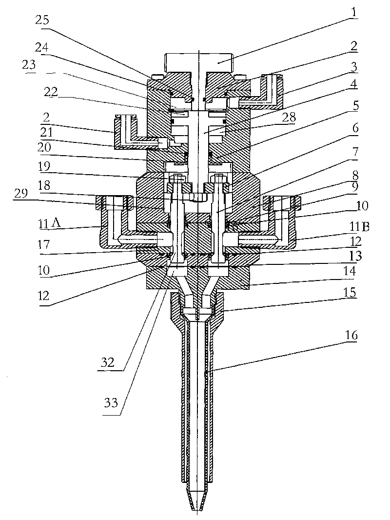
Embodiment 3

[0044] Such as figure 1 , figure 2 Shown, in embodiment 1, do further explanation on the basis of embodiment 2, the diameter of the first glue outlet hole 33 in the present embodiment is different from the diameter of described second glue outlet hole; The second piston The diameter of the tail of the tail is different from the diameter of the tail of the third piston; according to the use of different glue ratios, the diameter of the first glue outlet 33 in the valve body is different from the diameter of the second glue outlet. And the diameter of the tail portion of the second piston and the diameter of the tail portion of the third piston are set according to a certain ratio, and the ratio of the diameter of the first glue outlet hole 33 to the diameter of the second glue outlet hole is, 1:2, 1:3, until 1:100, or the ratio of the diameter of the second glue outlet 33 to the diameter of the first glue outlet is 1:2, 1:3, until 1:100 , the diameter of the second glue outl...


PUM


Abstract

The invention discloses a bi-component valve. A valve body comprises an upper valve body and a lower valve body; a heat part of the upper valve body is provided with an adjusting knob; the inside of the upper valve body is provided with a cylinder; a central part of the lower valve body is provided with a cavity; a first channel is arranged between the cylinder and the cavity; the bottom of the lower valve body is provided with at least one glue outlet hole which is communicated with the cavity; an upper side part of the upper valve body is provided with at least one first air inlet and at least one second air inlet which are distributed on two sides of a cross head part and are respectively communicated with the cylinder; and a lower side part of the lower valve body is provided with at least one first feeding device and at least one second feeding device which are respectively communicated with the cavity. The invention provides a bi-component valve having the advantages of quick and accurate glue dotting, clean glue stopping, and difficult damage to a sealing structure.

Description

technical field [0001] The invention relates to a two-component valve, in particular to a two-component valve provided with pneumatic control for improving the accuracy of precise dispensing. Background technique [0002] Nowadays, the application of two-component valves for gluing components in the packaging process is quite common. Traditionally, the structure of two-component valves is mostly composed of four base screws and four cover screws to connect a cover, a piston spring, A device composed of structural components such as a piston, a body, a needle valve, a valve seat body and a tail seat. When the two-component valve enters a glue, and the needle valve is driven by the piston, the glue can be pushed out by the needle valve to achieve the purpose of dispensing. The porous two-component valve device It is a two-component valve structure formed by bolting many components together with screws. In the dispensing process of the two-component valve, due to the continuo...

Claims


Application Information

Patent Timeline
IPC IPC(8): F16K11/07F16K31/122F16K41/04
Inventor 陈龙陈克银杨忠李高勇
Owner SHENZHEN AXXON AUTOMATION
Why Eureka
Try Eureka