Electrolysis water heater

An electrolytic water heater and relay technology, used in water heaters, fluid heaters, water/sewage treatment, etc., can solve the problems of high price, inconvenient disassembly, cleaning, poor safety and energy saving, etc. Thermal conductivity, time and energy saving, ease of operation and disassembly

Inactive Publication Date: 2010-04-21
周晓惕
View PDF0 Cites 6 Cited by
  • Summary
  • Abstract
  • Description
  • Claims
  • Application Information

AI Technical Summary

Problems solved by technology

[0002] There are two types of small electric water heaters on the market: one is the water storage type, which heats slowly and is bulky, and it is inconvenient to use because it is in the way of the faucet; the other is the instant heating type, which has high power and is easy to trip when starting , the water temperature is still difficult to meet the requirements when it is cold. And whether it is a water storage type or an instant heating type, it is poor in terms of safety and energy saving. In terms of electrolytic water devices, the technology is mostly imported from abroad, the price is expensive, and there are some Some defects, such as the produced alkaline electrolyzed water is cold, etc., so it is difficult to open the market in China. Although the original utility patent basically solved the above problems, some new problems appeared: such as the top cover is too small, In particular, the cathode plate is fixed on the water tank with bolts, which is not only not firm, but also inconvenient for disassembly and cleaning; , it is also difficult to keep a section of hose in the net sleeve parallel, which will seriously affect the quantity and quality of the water. In addition, when the water temperature is low and the current is small, the heat will be slower, and the temperature difference between the upper and lower water is also large. , seriously affecting disinfection and sterilization, etc.

Method used


Image

  • Electrolysis water heater
  • Electrolysis water heater
  • Electrolysis water heater

Examples


Embodiment Construction

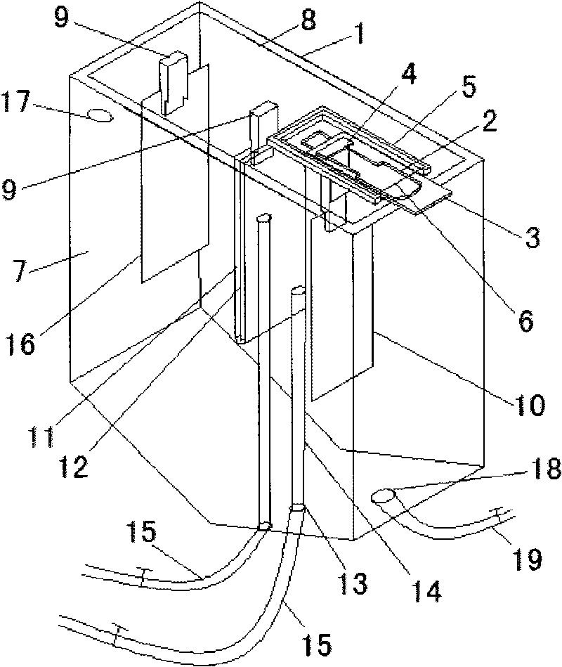
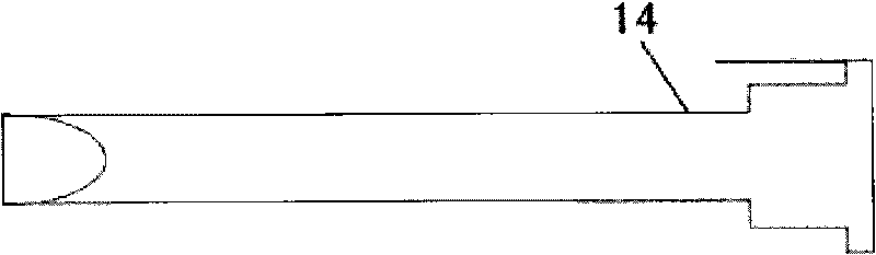
[0012] Such as figure 1 , figure 2 As shown, it includes end cover 1, T-shaped slot 2, control panel 3, slider 4, U-shaped step 5, cover plate 6, water tank 7, control circuit 8, hanger 9, fast heating anode plate 10, net sleeve 11. Cathode plate 12, water outlet hole 13, water guide pipe 14, water outlet hose 15, anode plate 16, feed hole 17, water inlet and outlet holes 18, water inlet and outlet hose 19, characterized in that: there is a T on the end cover 1 T-shaped slot 2 and T-shaped slot 2 are connected to the control panel 3, and one end of the control panel 3 has a hole that can be set on the upper end of the slider 4, and the upper end of the slider 4 is stuck in the T-shaped slot 2 and the slider 4 can be controlled by the control panel 3. The fast heating anode plate 10 is fixed on the lower end of the slider 4, and the distance between the pole plates can be adjusted by moving the slider 4, so that the size of the current can be adjusted. The three sides of the ...


PUM


Abstract

The invention relates to an electrolysis water heater. The electrolysis water heater is characterized in that one end of an end cover is provided with a T-shaped groove which is connected with an operation panel; one end of the operation panel is provided with a hole for sleeving the operation panel on the upper end of a slide block; the upper end of the slide block is blocked in the T-shaped groove, and the slide block is controlled by the operation panel; a fast heating anode plate is suspended at the lower end of the slide block; three faces of the T-shaped groove are connected with U-shaped steps which are further connected with a cover plate; the lower edge of the other end of the end cover is connected with a hanging bracket; the anode plate is fixed at the lower end of the hanging bracket; another hanging bracket is connected with the middle of the end cover to fix a cathode plate with a net sleeve at the lower end of the hanging bracket; and a plurality of water outlets are arranged under a water tank. The invention has the advantages that firstly, the performance of the electrolysis water heater is better, and the assembly and the disassembly are convenient; and secondly, by adding mineral substances in the water, not only the mineral substances such as calcium and the like needed by the human body can be supplemented, but also the sterilization effectiveness is improved.

Description

technical field [0001] The invention relates to an electric water heater, in particular to an electrolytic water heater. Background technique [0002] There are two types of small electric water heaters on the market: one is the water storage type, which heats slowly and is bulky, and it is inconvenient to use because it is in the way of the faucet; the other is the instant heating type, which has high power and is easy to trip when starting , the water temperature is still difficult to meet the requirements when it is cold. And whether it is a water storage type or an instant heating type, it is poor in terms of safety and energy saving. In terms of electrolytic water devices, the technology is mostly imported from abroad, the price is expensive, and there are some Some defects, such as the produced alkaline electrolyzed water is cold, etc., so it is difficult to open the market in China. Although the original utility patent basically solved the above problems, some new pro...

Claims


Application Information

Patent Timeline
Patent Type & Authority Applications(China)
IPC IPC(8): F24H1/20F24H9/18F24H9/20C02F1/461C02F1/00C02F1/50
Inventor 周晓惕
Owner 周晓惕
Why Eureka
Try Eureka