Method for visualizing fault state monitoring

A fault state and normal state technology, applied in the field of monitoring visualization, can solve the problems of inability to guarantee the effectiveness of monitoring, changes in observation parameters, and inability to achieve the effect of solving visualization problems

Inactive Publication Date: 2012-01-04
UNIV OF SHANGHAI FOR SCI & TECH
View PDF0 Cites 0 Cited by
  • Summary
  • Abstract
  • Description
  • Claims
  • Application Information

AI Technical Summary

Problems solved by technology

When there are three fault characteristic parameters to be monitored, the changes can only be observed through the three-dimensional space coordinate system. Since people are not very sensitive to changes in the position of three-dimensional space data points, the effectiveness of monitoring cannot be guaranteed.
When the monitored fault characteristic parameters are more than four, it will not be possible to observe the changes of the parameters through the visual method

Method used


Image

  • Method for visualizing fault state monitoring
  • Method for visualizing fault state monitoring
  • Method for visualizing fault state monitoring

Examples


Embodiment Construction

[0028] The present invention will be further described below in conjunction with the accompanying drawings and embodiments.

[0029] The visualization method of fault state monitoring of the present invention:

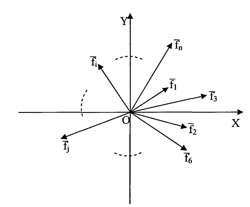
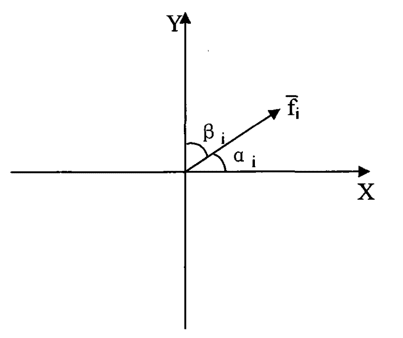
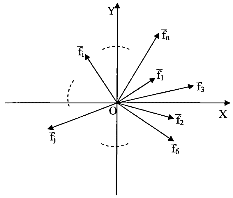
[0030] Let the fault characteristic parameter be F={f 1 , f 2 ,..., f n}, the origin of the XY plane coordinate system is (0, 0), each fault characteristic parameter f i (i=1, 2, ..., n) use a vector f whose starting point is the origin i (i=1, 2,...,n) means that n fault characteristic parameter vector directions are evenly distributed on the XY plane, and its direction is fixed, and its length depends on the fault characteristic parameter f i (i=1, 2, ..., n) size, such as figure 1 shown.

[0031] When the number of fault characteristic parameters is n, the interval angle of each fault characteristic parameter vector is 360° / n, so that they are evenly distributed on the XY plane. The arrangement order of the fault characteristic parameter vector is related to ...


PUM


Abstract

The invention relates to a method for visualizing fault state monitoring. The method comprises the following steps of: 1) setting fault characteristic parameters and vector directions; 2) determining the position of a composite vector CF; 3) visualizing a plurality of characteristic parameters on a two-dimensional plane; varying the position of the determined composite vector CF with the values of the fault characteristic parameters F={f1, f2,..., fn} to realize the visualization of the plurality of characteristic parameters on the two-dimensional plane. The method is used for an operator of a digit control machine to monitor the abnormal working state of the machine and brings about solution that correctly discriminates the working state of the digit control machine in the absence of monitoring samples of the abnormal working state; furthermore the problem of the visualization of the characteristic parameters is solved, and a new method is provided for monitoring the state of the digit control machine. The method is also suitable for monitoring the state of other devices.

Description

technical field [0001] The invention relates to a fault state monitoring method, in particular to a monitoring visualization method. Background technique [0002] The good flexibility and high machining accuracy of CNC machine tools make them the main equipment in modern production systems. And with the improvement of the automation degree of the production system, the role played by the CNC machine tool is also increasing. Once a failure occurs, the loss caused to the production system is also increasing. Therefore, it is becoming more and more important to carry out condition monitoring and fault diagnosis on processing equipment. The main purpose of condition monitoring of equipment is to ensure the safe operation of the processing system, avoid equipment failure, ensure processing quality, and improve production efficiency and equipment utilization. In order to effectively monitor the state of the CNC machine tool, it is often necessary to judge the working state of th...

Claims


Application Information

Patent Timeline
Patent Type & Authority Patents(China)
IPC IPC(8): G05B19/406
Inventor 李郝林蒋丽琳
Owner UNIV OF SHANGHAI FOR SCI & TECH
Why Eureka
Try Eureka