Grass trimmer

A lawn mower and mowing head technology, applied in the field of lawn mowers, can solve the problem of visualization, reduce root wear and avoid friction.

Active Publication Date: 2021-10-12
NANJING CHERVON IND
View PDF10 Cites 0 Cited by
  • Summary
  • Abstract
  • Description
  • Claims
  • Application Information

AI Technical Summary

Problems solved by technology

[0005] The purpose of the present invention is to provide a mowing machine that can reduce the risk of mowing rope breakage, solve the problem of mowing rope visualization, and effectively improve the aerodynamic noise of the mowing rope at the same time

Method used


Image

  • Grass trimmer
  • Grass trimmer
  • Grass trimmer

Examples


Embodiment 1

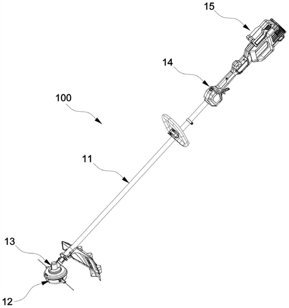
[0041] This embodiment discloses a grass trimmer 100, such as figure 1 and figure 2 As shown, the mowing machine 100 includes a connecting rod 11 , a mowing head 12 , a driving part 13 , an operating part 14 and a coupling part 15 . Wherein, one end of the connecting rod 11 is connected to the driving part 13 , and the other end is connected to the operating part 14 . The coupling portion 15 is disposed at an end of the operating portion 14 away from the connecting rod 11 . The mowing head 12 is connected to the driving part 13 and can mow grass when being driven; The operation part 14 is operable by a user to control the mower 100 . As an implementation method, the mowing machine 100 can not only reduce the risk of the mowing rope 121 breaking from the root, reduce maintenance and replacement costs, prolong the service life of the mowing machine 100, but also realize the visualization of the mowing rope 121, and effectively Weaken the aerodynamic noise when the grass rop...

Embodiment 2

[0055] This embodiment provides a lawn trimmer 100, which is basically the same as the lawn trimmer 100 in Embodiment 1, the only difference being that the structure of the protective structure 124 of the grass trimmer 100 in this embodiment is different.

[0056] Specifically, the protective structure 124 in this embodiment is a split structure, which includes a first body and a second body, one side of the first body is rotatably connected to one side of the second body, and the other side of the first body One side and the other side of the second body are opened or locked by a locking mechanism (not shown in the figure).

[0057] During actual assembly, the locking mechanism is unlocked, the first body and the second body are opened, the mowing rope 121 is put into the through channel, and then the first body and the second body are fastened together, and the protective structure 124 is locked by the locking structure. locking, so as to realize the fixing of the mowing rop...


PUM


Abstract

The invention belongs to the technical field of grass trimmers, and discloses a grass trimmer. The grass trimmer comprises a connecting rod, a grass trimming head and an operating portion, wherein one end of the connecting rod is connected with the grass trimming head, the other end of the connecting rod is connected with the operating portion, and the grass trimming head comprises a grass trimming rope, a reel, a shell and a streamline protection structure; the reel is used for winding the grass trimming rope and can rotate around a first axis; the shell is provided with an accommodating cavity for accommodating at least part of the reel, and a threading hole for the grass trimming rope to extend out of the outer side of the shell is formed in the shell; and the streamline protection structure comprises a head part and a tail part and is provided with a through channel for the grass trimming rope to penetrate through, the head part is connected to the shell, and the through channel is used for connecting the grass trimming rope penetrating out of the threading hole and enabling the grass trimming rope to be exposed out of the tail part of the protection structure. By arranging the protection structure, the supporting and protecting effects on the grass trimming rope are achieved, the grass trimming rope can be prevented from being curled, and the risk that the grass trimming rope is broken from the root is reduced; the problem of visualization of the grass trimming rope is solved; and meanwhile, the streamline protection structure can effectively reduce pneumatic noise generated when the grass trimming rope works.

Description

technical field [0001] The invention relates to the technical field of mowers, in particular to a mower. Background technique [0002] The mower is one of the commonly used garden tools, and is very popular among gardeners because of its small size, light weight, and easy operation. Common lawn trimmers usually include three parts: a mowing head, a handle, and an operating rod connecting the mowing head and the handle, and the user performs the mowing operation by holding the handle. The high-speed rotation of the mowing head drives the mowing rope installed on it to rotate rapidly to form an annular cutting wheel to realize the cutting of the grass stem. [0003] When the existing mowing rope rotates at high speed, the mowing rope is easily drawn to hard obstacles such as fire hydrants and shrubs and curls, causing thread breakage, and the high-speed mowing rope frequently rubs against the shell of the mowing head. It is easy to wear and tear and cause the mowing rope to ...

Claims


Application Information

Patent Timeline
Patent Type & Authority Applications(China)
IPC IPC(8): A01D34/416A01D75/00A01D75/18
CPCA01D34/416A01D34/4167A01D75/00A01D75/18A01D34/84A01D34/90
Inventor 李立戴开超
Owner NANJING CHERVON IND
Why Eureka
Try Eureka