Design method of Ethernet device stack system

A technique for stacking systems, design methods

Active Publication Date: 2010-04-28
丁贤根
View PDF0 Cites 26 Cited by
  • Summary
  • Abstract
  • Description
  • Claims
  • Application Information

AI Technical Summary

Problems solved by technology

[0011] This technology has the advantage of small message forwarding delay, but it also has the following disadvantages: 1) The message forwarding between two stack units can only pass through the n

Method used


Image

  • Design method of Ethernet device stack system
  • Design method of Ethernet device stack system
  • Design method of Ethernet device stack system

Examples


Embodiment Construction

[0067] Specific embodiments of the present invention will be described in detail below in conjunction with the accompanying drawings.

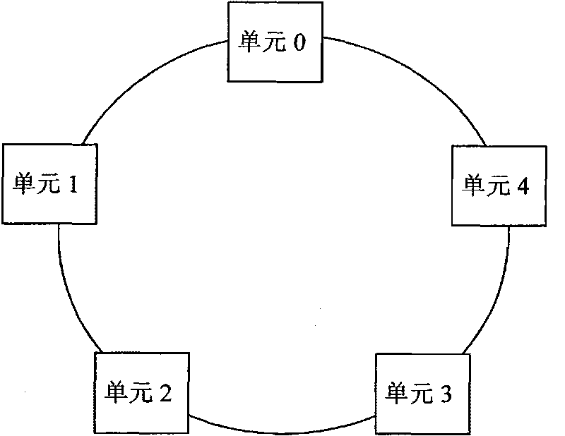
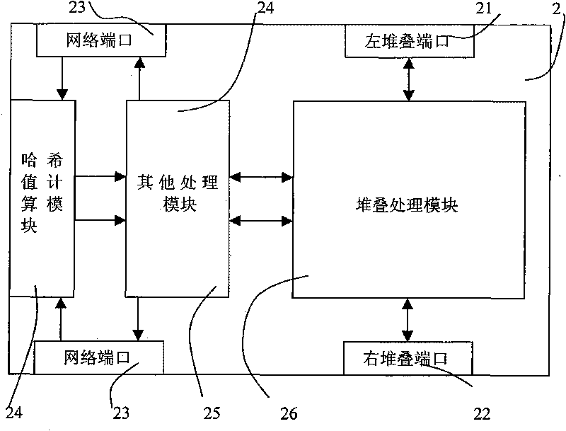
[0068] figure 2 One embodiment of the invention is shown. This embodiment is a stacking system provided by the present invention, and the stacking system is composed of two or more stacking units. Each stack unit has a left stack port, a right stack port, and a network port. Adjacent stacking units are connected through stacking links to form a ring-shaped stacking system. The present invention does not limit the stacking port rate. In Gigabit Ethernet equipment, it is recommended to use ports with a rate greater than 1G. Stacking ports are divided into left stacking ports and right stacking ports. The number of left and right stacking ports is not limited.

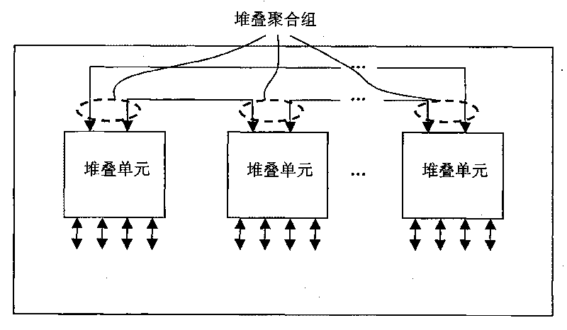
[0069] In this embodiment, by using the link aggregation technology, all left stack ports and right stack ports are aggregated into an aggregation group, which we call a stack aggrega...


PUM


Abstract

The invention relates to a design method for stacking Ethernet devices. In an annular-structure stack system, on the basis of the thought of link integration, all the stack ports in two directions of a stack unit are added to the same stack aggregation group; the destination of messages which are sent to the other stack unit is set to be the stack aggregation group; and then, a stack port is found out from a port mapping table of the stack aggregation group according to the hash values of the messages so as to forward the messages from this port. When a stack link at some part fails, the stack system only needs to modify the configuration of two stack units which are next to the fault and remove the failed port from the stack aggregation group so as to prevent the messages from being forwarded from the failed port and forward the messages from other fault-free ports. Because other stack units of the stack system do not need to sense the fault, the method restricts the influence of the failed stack port on the entire stack system, and enables the fault of the stack system to be repaired quickly.

Description

(1) Technical field [0001] The invention relates to the field of data communication, in particular to an Ethernet device, especially an Ethernet device with a stacking function. (2) Background technology [0002] With the development of Ethernet technology, Ethernet has been widely used in enterprise networks and has occupied most of the enterprise network market. Ethernet equipment has also been developed rapidly and widely used. [0003] Due to the limited number of ports and forwarding bandwidth of each Ethernet device, in order to form a larger network, it is necessary to use multiple Ethernet devices to provide greater network bandwidth and more network ports. There are two mainstream ways to expand ports and bandwidth now: 1) Ethernet device cascading. 2) Ethernet device stacking. [0004] Because the Ethernet device stacking system simplifies the network topology and has the advantages of simple and convenient management, it has been widely used. Stacking is to co...

Claims


Application Information

Patent Timeline
IPC IPC(8): H04L12/42H04L12/56H04L45/02
Inventor 颜小波何慈康郑有为丁贤根
Owner 丁贤根
Why Eureka
Try Eureka