
Dust collection mechanism on air duct cleaning robot and air duct cleaning robot

A technology for cleaning robots and dust collection mechanisms, which is applied in the direction of cleaning hollow objects, cleaning methods and utensils, chemical instruments and methods, etc., and can solve problems such as poor control effects, affecting work efficiency, and affecting dust collection effects, so as to ensure suction Dust effect, easy installation and maintenance, good maneuverability

Inactive Publication Date: 2011-09-14
ZHEJIANG UNIV OF TECH
View PDF0 Cites 0 Cited by
  • Summary
  • Abstract
  • Description
  • Claims
  • Application Information

AI Technical Summary

Problems solved by technology

In case of an obstacle, if the suction port cannot be lifted or turned in time, it will affect the progress of the car; in case of a depression, the suction port will leave the inner surface of the air duct, and the suction will be weakened, which will affect the dust collection effect
Only when the suction port is close to the surface, the dust suction effect is the best; if the adjustment is too much, the car body will be jacked up; if the adjustment is not enough, the suction will drop; manual control of the rocker arm lifts frequently, seriously affecting the work efficiency and control effect not good too

Method used


Image

  • Dust collection mechanism on air duct cleaning robot and air duct cleaning robot
  • Dust collection mechanism on air duct cleaning robot and air duct cleaning robot
  • Dust collection mechanism on air duct cleaning robot and air duct cleaning robot

Examples


Embodiment 1

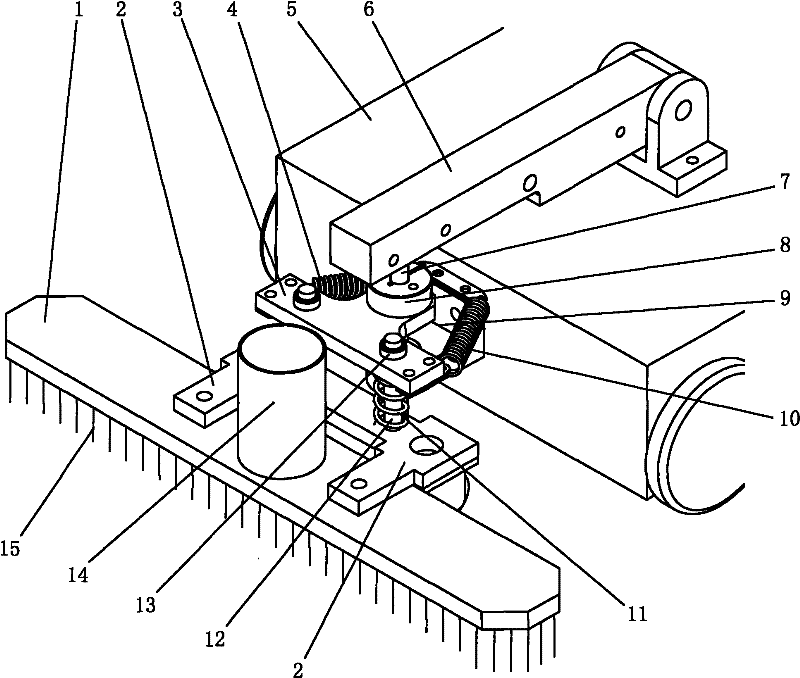
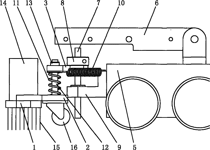
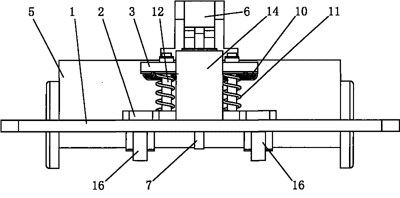
[0021] like Figure 1 to Figure 4 The dust suction mechanism on the air duct cleaning robot shown includes a dust suction port 1 and a trolley body 5, the trolley body 5 is hinged with a rocker arm 6, and the rocker arm 6 is lifted and positioned under the control of a driving mechanism; The front of the trolley body 5 is fixed with a connecting seat 9, and the connecting seat 9 is connected with a long guide rod 7. The lower end of the long guide rod 7 passes through the connecting seat 9 and can rotate and vertically move up and down relative to the connecting seat 9. The upper end of the guide rod 7 is covered with a floating plate 3, the floating plate 3 is fixedly connected with the long guide rod 7 through the fixed ring 8, and the left and right sides of the floating plate 3 are respectively connected to the connecting seat 9 or the trolley through the extension springs 4, 10. The car body 5 is connected (due to the effect of the tension spring, the floating plate is al...

Embodiment 2

[0026] An air duct cleaning robot, comprising a trolley body, the front of the trolley body is provided with a dust suction mechanism as described in Embodiment 1.


PUM


Abstract

The invention discloses a dust collection mechanism on an air duct cleaning robot, which comprises a dust collection port and a car body, wherein a rocker arm is hinged on the car body, and the rocker arm is ascended, descended and positioned under the control of a driving mechanism; a connecting base is fixedly arranged in front of the car body, a floating plate is connected on the connecting base through a long guide bar, the floating plate and the connecting base are vertically connected in a sliding manner and can rotate relatively, the rocker arm can impose the downward pressure on the floating plate, and the left side and the right side of the floating plate are connected with the connecting base or the car body through tension springs respectively; and the dust collection port is fixed on a press plate, universal wheels are arranged below the press plate, the press plate and the floating plate are vertically connected in the sliding manner, a compression spring is directly arranged between the press plate and the floating plate, the upper end of the compression spring leans against the floating plate, and the lower end of the compression spring leans against the press plate. The invention further discloses the air duct cleaning robot containing the dust collection mechanism. The technical scheme has a self-adaptive structure, thereby being capable of carrying out self-adjustment according to the complicated situations of elbows, uplifts, depressions and the like in a pipeline of an air duct and further ensuring the good dust collection effect.

Description

technical field [0001] The invention belongs to the technical field of pipeline cleaning, and relates to an air duct cleaning robot (remote control trolley) for performing dust suction operations in central air-conditioning ducts, in particular to a dust collection mechanism installed on the air duct cleaning robot (remote control trolley) . Background technique [0002] The central air-conditioning and ventilation system undertakes the important task of delivering cold, warm and fresh air to people. However, because the air-conditioning duct is relatively closed, the temperature and humidity inside are very suitable for the growth and reproduction of microorganisms, especially fungi. If the central air conditioner is not cleaned for a long time, a large amount of dust will easily accumulate in the ventilation duct, and insect corpses that enter in the future will easily breed a large number of harmful bacteria. After the human body inhales it, the mild ones feel unwell, an...

Claims


Application Information

Patent Timeline
Patent Type & Authority Patents(China)
IPC IPC(8): B08B9/04B08B9/035
Inventor 童建平隋成华余文唐轶峻徐丹阳
Owner ZHEJIANG UNIV OF TECH
Learn More