
Laser generating device of laser marking machine

A laser marking machine and laser generation technology, applied in the direction of laser cooling devices, lasers, phonon exciters, etc., can solve problems such as condensation of laser modules, achieve the effects of increasing service life, ingenious ideas, and highlighting substantive features

Inactive Publication Date: 2010-05-05
瑞安市博业激光应用技术有限公司
View PDF0 Cites 7 Cited by
  • Summary
  • Abstract
  • Description
  • Claims
  • Application Information

AI Technical Summary

Problems solved by technology

[0003] In view of the problems existing in the current known technologies, the technical problem to be solved by the present invention is to provide a laser with a simple structure, which can solve the problem of dew condensation in the laser module, increase the service life of the laser module, and improve the working stability and laser power stability of the laser module. Marking machine laser generator

Method used


Image

  • Laser generating device of laser marking machine
  • Laser generating device of laser marking machine

Examples


Embodiment Construction

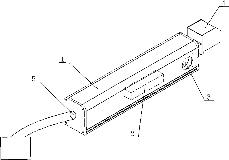
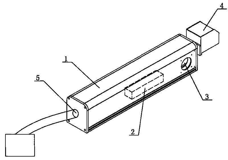
[0009] As shown in the accompanying drawings, the laser generating device of the laser marking machine has a casing 1, and one side of the casing 1 is provided with a vibrating lens 4 (the function of the vibrating lens is to adjust the direction of the laser emitted by the laser module). The casing 1 is a closed shell with an air inlet 5 and an air outlet 3, the air inlet 5 communicates with the air conditioning cooling system, the air inlet 5 is located on the side of the casing 1 away from the vibrating head 4, and the air outlet 3 It is arranged on the side of the casing 1 close to the vibrating head 4, and the laser module 2 is arranged in the casing 1 (the cooling of the laser module adopts water cooling).

[0010] When the laser marking machine is working, the laser module is in the working environment with the air supply of the air conditioning cooling system, and its exhaust is discharged through the air outlet. The ambient temperature is stable and the humidity is low...


PUM


Abstract

The invention discloses a laser generating device of a laser marking machine, which is provided with a housing. A laser module is arranged in the housing, and a shaking lens is arranged at one side of the housing. The laser generating device is characterized in that the housing is a closed shell provided with an air inlet and an air outlet; and the air inlet is communicated with an air-conditioner cooling system. The invention has simple structure and smart conception, and completely solves the condensation problems of the laser module in prior technique, prolongs the service life of the laser module and improves the work stability of the laser module and the power stability of the laser.

Description

【Technical field】 [0001] The invention relates to a laser device, in particular to a laser generating device of a laser marking machine. 【Background technique】 [0002] The laser marking machine is mainly used for marking the surface of the material, that is, using a laser to mark the text or pattern with fine and high-precision characteristics on the surface of the material. The laser module is the core component of the laser marking machine. The laser module is generally installed in the casing of the laser generator. The working environment in the casing is connected to the outside working environment. The problem with the above structure is that when the laser module is working, it will produce A large amount of heat needs to be cooled by a cooling system to keep the temperature of the laser module constant. Each working component in the laser module will generate condensation, and the consequence is that the life of the working components in the laser module will be sh...

Claims


Application Information

Patent Timeline
Patent Type & Authority Applications(China)
IPC IPC(8): H01S3/00H01S5/00H01S3/04H01S5/024
Inventor 夏青松聂奎
Owner 瑞安市博业激光应用技术有限公司
Learn More