Multifunctional intelligent transformer cabinet

A variable-motor and multi-functional technology, which is applied in substation/distribution device housing, substation/switchgear cooling/ventilation, etc., can solve the problems of energy waste, inability to adjust, single heat dissipation mode of heat dissipation system, etc., and achieve enhanced dust prevention effect, avoid damage, effect of avoiding waterlogging problems

Active Publication Date: 2019-05-03
安徽辉宝智能装备有限责任公司
View PDF8 Cites 8 Cited by
  • Summary
  • Abstract
  • Description
  • Claims
  • Application Information

AI Technical Summary

Problems solved by technology

[0003] The transformer cabinet is a relatively important component part in the substation. It plays a very good external protection role for the power distribution equipment. For some high-precision substations, in order to better control the greenhouse temperature in the transformer cabinet, thereby reducing In case of damage to internal substation equipment, heat dissipation and heating components are usually added for temperature and humidity control, but the existing substation cabinets with heat dissipation and heating components still have some shortcomings, for example, they cannot achieve rapid stability in extremely cold weather The heat dissipation mode of the heat dissipation system is relatively single, and it cannot be adjusted to different heat dissipation modes according to different temperature values, resulting in energy waste; in addition, the distribution of heat dissipation holes in the traditional transformer cabinet is also relatively simple, which cannot meet different heat dissipation modes needs

Method used


Image

  • Multifunctional intelligent transformer cabinet
  • Multifunctional intelligent transformer cabinet
  • Multifunctional intelligent transformer cabinet

Examples


Embodiment Construction

[0027] The following will clearly and completely describe the technical solutions in the embodiments of the present invention with reference to the accompanying drawings in the embodiments of the present invention. Obviously, the described embodiments are only some, not all, embodiments of the present invention. Based on the embodiments of the present invention, all other embodiments obtained by persons of ordinary skill in the art without making creative efforts belong to the protection scope of the present invention.

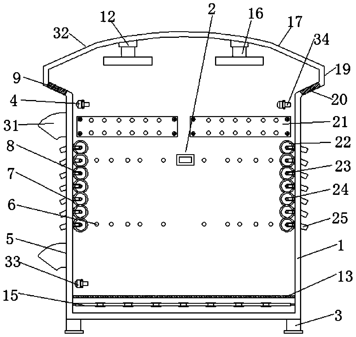
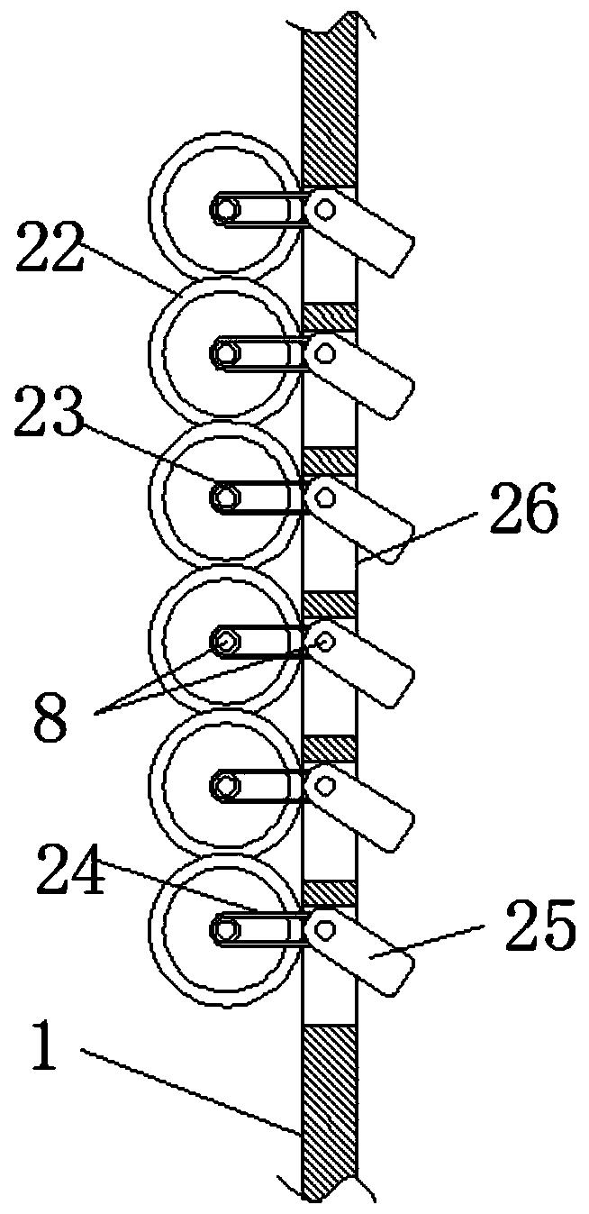
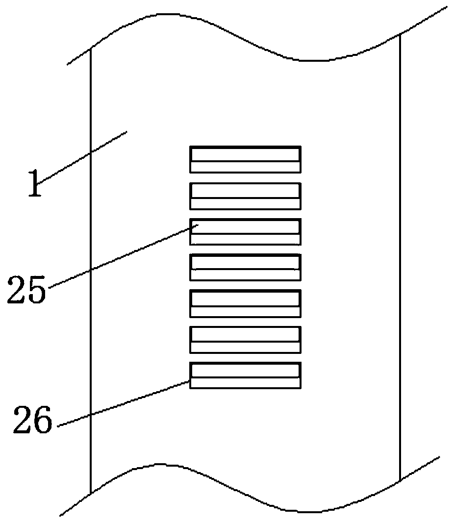
[0028] Such as figure 1As shown, a multifunctional intelligent transformer cabinet includes a cabinet body 1, support feet 3 fixed on the four corners of the bottom surface of the cabinet body 1, and an electrical appliance fixing plate 21 fixedly installed inside the cabinet body 1, and an inner wall of the cabinet body 1 is also provided There are a plurality of installation holes 6, and the upper and lower ends of the side wall of the cabinet body 1 are pro...


PUM


Abstract

The invention discloses a multifunctional intelligent transformer cabinet. The cabinet comprises a cabinet body. The top end of the cabinet body is fixedly connected with a top cover. A circle of strip-shaped vent holes are also formed in the side wall of the top cover. Fans are fixed on two sides of the inner wall of the top end of the top cover. A plurality of groups of electric heating wires are fixed at the lower part inside the cabinet body. A first temperature sensor is further mounted on the lower end part, close to the electric heating wires, of the inner wall of the cabinet body. A second temperature sensor is installed at the upper end, away from the electric heating wires, of the inner wall of the cabinet body. A first temperature controller and a corresponding time controller are further installed in the cabinet body. The side walls of the two ends of the cabinet body are each provided with a row of strip-shaped heat dissipation holes. Air guide plates are movably installedon the strip-shaped heat dissipation holes. The air guide plates can adjust the opening degrees of the strip-shaped heat dissipation holes. In extremely cold weather, the interior of the cabinet bodycan be rapidly and stably heated, so that the rapid and uniform heating effect in the cabinet body can be achieved within a short period of time. In hot weather, the cabinet body can be adjusted to be in different heat dissipation modes according to different temperature values in the cabinet body.

Description

technical field [0001] The invention relates to the technical field of electrical transformation cabinets, in particular to a multifunctional intelligent electrical transformation cabinet. Background technique [0002] Box-type substation, also known as prefabricated substation or prefabricated substation. It is a kind of high-voltage switchgear, distribution transformer and low-voltage power distribution device. It is a factory prefabricated indoor and outdoor compact power distribution device arranged according to a certain wiring scheme, which is to organically combine functions such as transformer step-down and low-voltage power distribution. Together, they are installed in a moisture-proof, rust-proof, dust-proof, rodent-proof, fire-proof, theft-proof, heat-insulated, fully enclosed, and movable steel structure box, which is especially suitable for urban network construction and transformation. A brand new substation. [0003] The transformer cabinet is a relatively i...

Claims


Application Information

Patent Timeline
Patent Type & Authority Applications(China)
IPC IPC(8): H02B1/56H02B1/28
Inventor 李贵
Owner 安徽辉宝智能装备有限责任公司
Why Eureka
Try Eureka