
Circuit for multi-path LED constant current driving

A constant current driving, rectifying and filtering circuit technology, applied in the direction of circuit layout, lamp circuit layout, electric light source, etc., can solve the problems of large power consumption of linear adjustment tubes, heat generation of LED drivers, etc., and achieve low cost, high reliability, and high efficiency. high effect

Inactive Publication Date: 2010-05-05
INVENTRONICS HANGZHOU
View PDF0 Cites 32 Cited by
  • Summary
  • Abstract
  • Description
  • Claims
  • Application Information

AI Technical Summary

Problems solved by technology

Although the circuit cost of this solution is low and the current sharing of each LED is good, short circuit is a common failure mode of LEDs. When the voltage difference of multiple LEDs is relatively large, the power consumption of the linear adjustment tube is very large, which makes the LED driver seriously heat.

Method used


Image

  • Circuit for multi-path LED constant current driving
  • Circuit for multi-path LED constant current driving
  • Circuit for multi-path LED constant current driving

Examples


Embodiment Construction

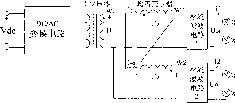
[0048] Reference image 3 , A circuit suitable for multi-channel LED constant current drive. In the case of two LED loads, the secondary winding of the main transformer is a single winding, characterized in that: the current-sharing transformer includes Two windings W1 and W2, the secondary winding W of the main transformer T One end of the winding W1 is connected to the same-named end of the winding W1 and the non-same-named end of the winding W2, and the non-same-named end of the winding W1 is connected to the winding W T The other end is used as the input end of the rectifier filter circuit 1, the end of the winding W2 and the winding W T The other end of the rectifier filter circuit 2 is used as the input terminal, and the rectifier filter circuits 1 and 2 are respectively connected to two LED loads.

[0049] in image 3 In the circuit shown, the output current i of the transformer w1 And i w2 The two windings W1 and W2 of the current-sharing transformer respectively flow throu...


PUM


Abstract

The invention discloses a circuit for a multi-path LED constant current driving, comprising a DC / AC converting circuit, a main transformer, a current sharing transformer, a multi-path rectification filter circuit and LED loads, the circuit for the multi-path LED constant current driving is characterized in that: the input direct voltage is converted into alternating voltage by the DC / AC converting circuit, the alternating voltage is isolated by the main transformer and then is input to the current sharing transformer, the current sharing transformer has the function of current sharing for each path of the current, and each path of the current is respectively output to each LED load after passing through each rectification filter circuit. The circuit for the multi-path LED constant current driver has the beneficial effects that: firstly, the balance of load current among multi-path LEDs is realized by a first level converting circuit; secondly, the current sharing control is automatically realized by the current sharing transformer without an extra control circuit, the reliability is high; thirdly, the efficiency of realizing current sharing is high by the current sharing transformer, the loss of realizing current sharing is less when the dropout voltage of two paths of the LEDs is high.

Description

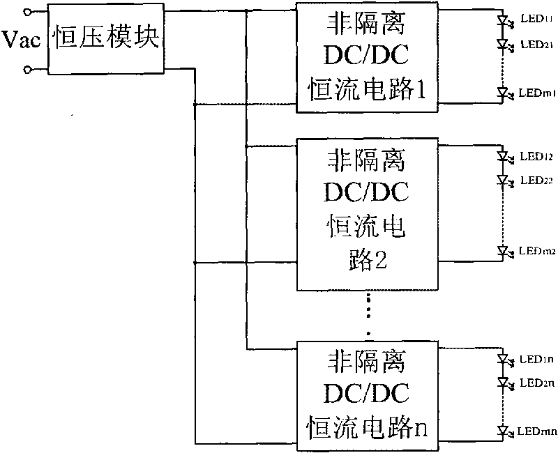
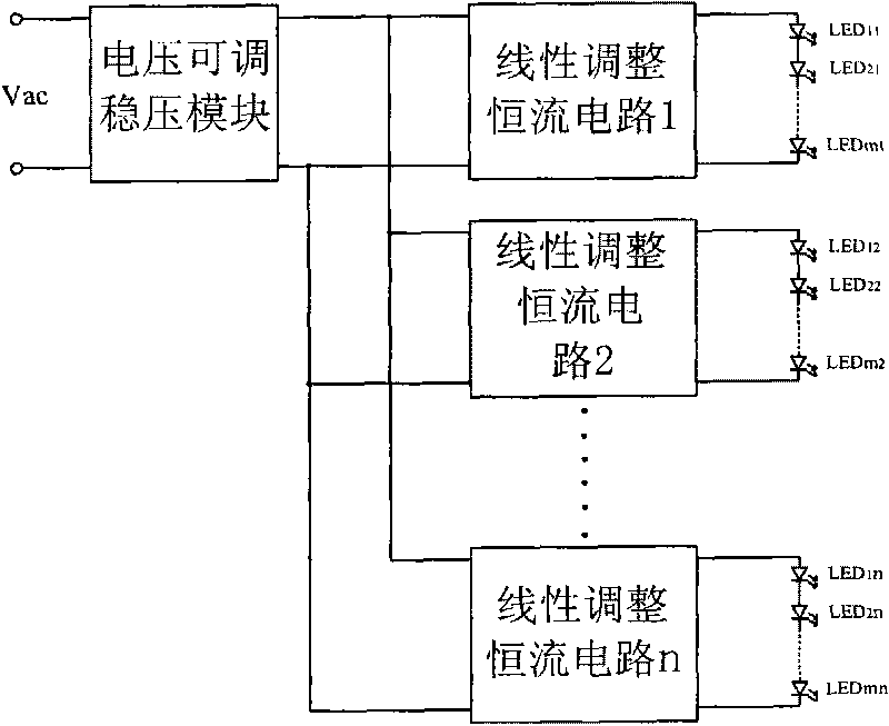
Technical field [0001] The invention relates to a circuit suitable for multi-channel LED constant current driving. Specifically, it should be a way to achieve multi-channel LED load current balance through a current-sharing transformer. Background technique [0002] For the application of LED multi-channel constant current control driver, the most commonly used solutions are: 1. Constant voltage module + multi-channel non-isolated DC / DC constant current circuit such as BUCK circuit; 2. Voltage adjustable regulator module + multi-line adjustment Constant current circuit. [0003] For the first option, refer to figure 1 , The output of the constant voltage module is used as the input of multiple constant current circuits, and each constant current circuit is individually controlled for constant current, which can easily ensure the current sharing of the multiple output currents. However, because the voltage of the constant voltage module and the voltage of the LED generally have a ...

Claims


Application Information

Patent Timeline
IPC IPC(8): H05B37/02F21V23/00F21Y101/02F21Y115/10
CPCY02B70/1491Y02B70/10
Inventor 葛良安姚晓莉华桂潮吴新科任丽君
Owner INVENTRONICS HANGZHOU
Learn More