Electric pipe bending machine

A pipe bending machine and pipe bending technology, which is applied in the field of electric pipe bending machines, can solve the problems of low work efficiency, low labor intensity, and high labor intensity, and achieve the effects of good pipe bending effect, low power requirement, and low cost

CN101704042AInactive Publication Date: 2010-05-12王克启
0 Cites 15 Cited by

Patent Information

Authority / Receiving Office
CN · China
Patent Type
Applications(China)
Current Assignee / Owner
Publication Date
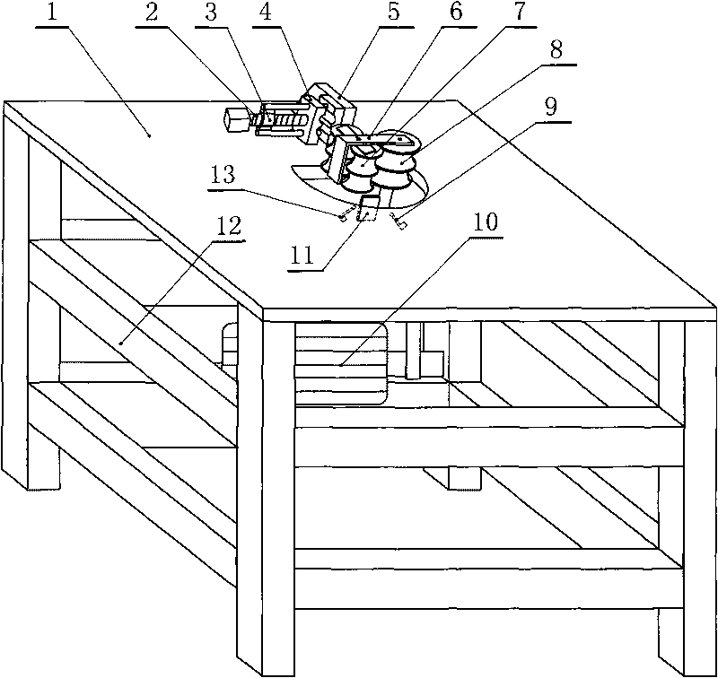
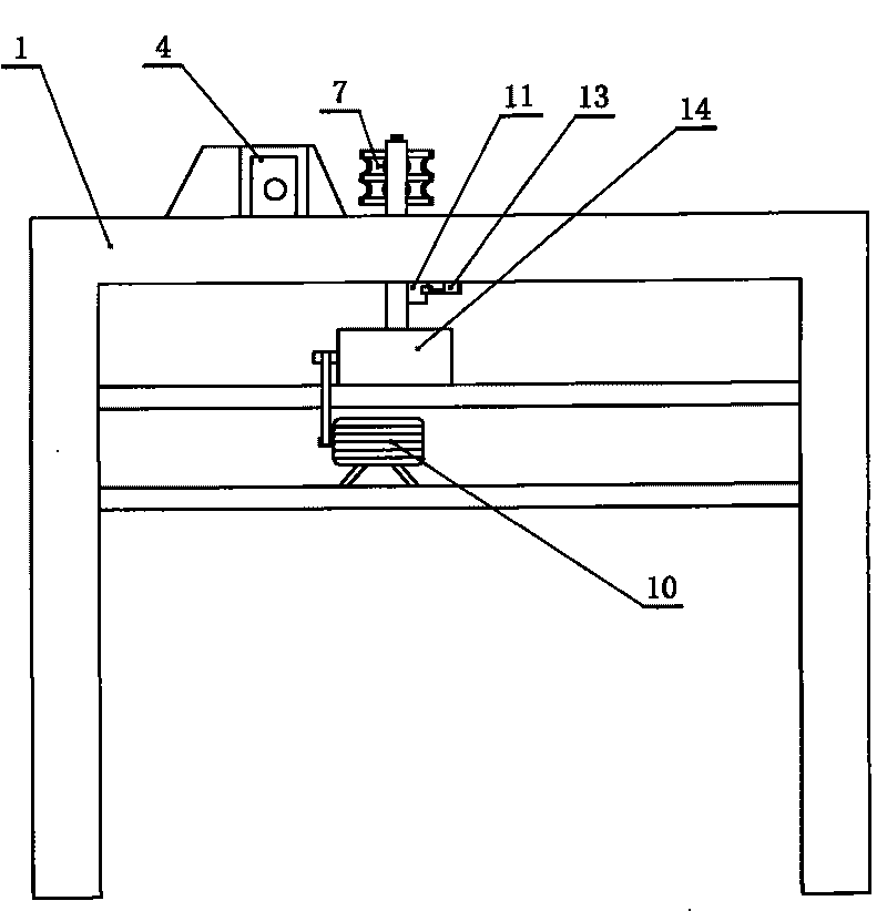
2010-05-12
Estimated Expiration
Not applicable · inactive patent

Smart Images

  • Figure 1
    Figure 1
  • Figure 2
    Figure 2
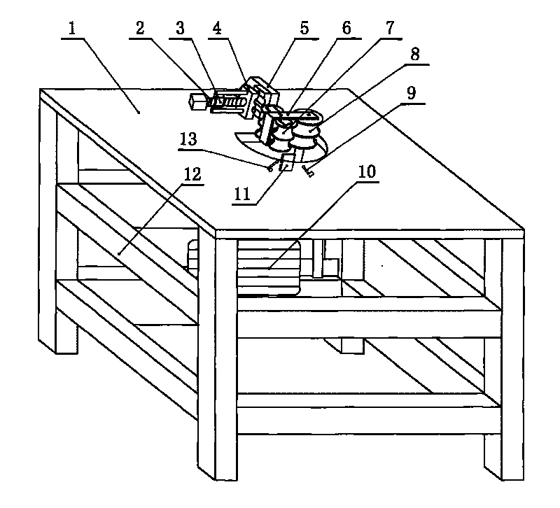
  • Figure 3
    Figure 3
Patent Text Reader

Abstract

The invention relates to an electric pipe bending machine which comprises a frame. An operation platform is arranged on the frame, and a bending pipe fixing frame is fixedly installed on the operation platform. The bending pipe fixing frame comprises a fixed press block, wherein the fixed press block is fixedly installed on the operation platform, and the inner side of the fixed press block is provided with a groove; a screw rod frame is fixedly installed on the operation platform, and a screw rod is installed on the screw rod frame; one end of the screw rod is connected with a moving press block, and the inner side of the moving press block is provided with a groove; the operation platform is provided with an opening, and a motor is arranged under the operation platform; the motor is connected with a reduction box, and an output shaft of the reduction box passes upwards through the opening on the operation platform vertically to be connected with a main wheel of a bending pipe; a bending pipe U-shaped bracket is fixedly connected to the main wheel of the bending pipe, and two bending pipe secondary wheels are connected between the inner side of the bending pipe U-shaped bracket and the main wheel of the bending pipe by pins; a travel switch baffle plate is fixedly connected to the output shaft of the reduction box, and an arriving sensor and a return sensor are installed under the operation platform. The invention has the characteristics of low rotating speed, small inertia, low power requirement of the motor and low cost.
Need to check novelty before this filing date? Find Prior Art

Description

technical field

[0001] The invention relates to an electric pipe bender. Background technique

[0002] There are two types of traditional pipe bending: 1. Mechanical production: hydraulic pressure is used to produce machinery, which is complex and has a large power package. Each machine costs 30,000 to 35,000 yuan, and the power used is 40 million per hour. 2. Manpower production: high labor intensity and low work efficiency, normal male workers can produce 1000 per day, if machine production can produce 1800 per day, the labor intensity of mechanical production is low, and female workers can also operate. Contents of the invention

[0003] The object of the present invention is to provide a labor-saving and environment-friendly electric pipe bender.

[0004] To achieve the above object, the technical solution adopted in the present invention is:

[0005] An electric pipe bender, comprising: a frame, an operation table is arranged on the top of the frame, and the feature...

Examples

Embodiment Construction

[0010] The present invention will be further described below in conjunction with accompanying drawing and specific embodiment:

[0011] An electric pipe bender, such as figure 1 , figure 2 As shown, it includes: a frame 12, and an operation console 1 is arranged on the top of the frame 12. An elbow fixed frame is fixedly installed on the console 1, and the curved pipe fixed frame includes: a fixed briquetting block 5, a screw frame 3, a movable briquetting block 4, and the like. The fixed briquetting block 5 is fixedly installed on the console 1, and the inboard of the fixed briquetting block 5 has grooves. A screw frame 3 is fixedly installed on the console 1, and the top and bottom of the screw frame 3 are connected with guide rods, and the guide rod passes through the movable briquetting block 4 and is connected with the fixed briquetting block 5 . Screw rod 2 is housed on the screw rod frame 3, and an end of screw rod 2 is connected with movable briquetting block 4, an...