

Diaphragm wall joint flexible water stop installing device and method
A technology of underground diaphragm wall and installation device, which is applied in water conservancy projects, underwater structures, artificial islands, etc., can solve the problems of increased cost, low rigidity, long time interval, etc. The effect of joint connection, easy installation and removal
- Summary
- Abstract
- Description
- Claims
- Application Information
AI Technical Summary
Problems solved by technology
Method used
Image

Examples
Embodiment Construction
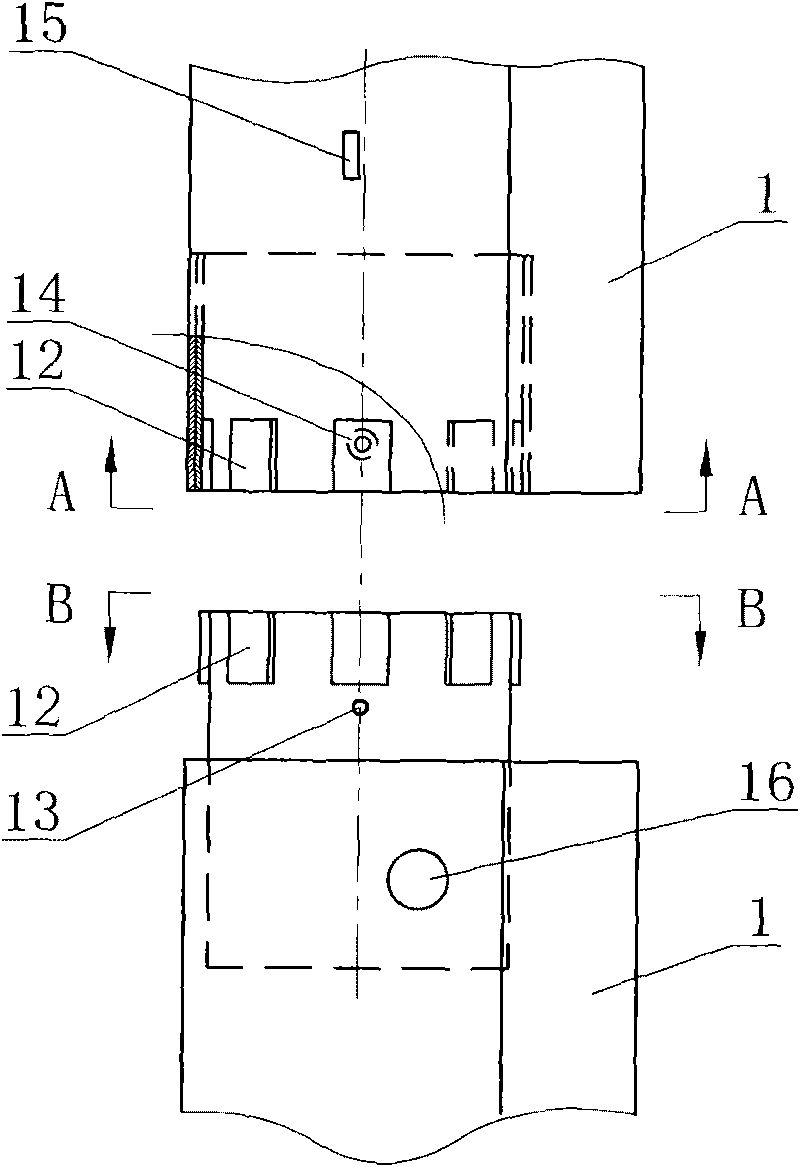
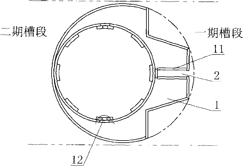
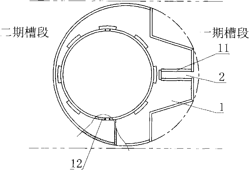
[0021] Such as Figure 1 to Figure 5 As shown in the utility model, a flexible waterstop installation device and method for an underground diaphragm wall joint described in the utility model, the installation device is a joint pipe structure 1 made of steel plate or section steel with a ratio of width and thickness close to 1, The side in contact with the concrete is provided with at least one installation groove 11 where the rubber waterstop 2 can be installed, and the width of the opening of the installation groove is slightly smaller than the width of the cavity. Among them, in order to ensure convenient transportation, the length of the above-mentioned joint pipe structure 1 is consistent with the length that can be transported by trucks, and the two ends of each joint pipe structure are provided with corresponding fast-rotating bayonet connection structures 12; in order to facilitate on-site construction and To disassemble and assemble each joint pipe structure, the two e...
PUM
 Abstract
Description
Claims
Application Information