Permanent magnet operating mechanism for 50 kA vacuum circuit breaker

A vacuum circuit breaker and permanent magnet operating technology, which is applied to high-voltage air circuit breakers, circuits, electrical components, etc., can solve the problems of increased operating power consumption, increased cost, and easily broken magnets, and achieves high retention and high performance. Reliable, low operating effort results

Inactive Publication Date: 2010-05-12
上海安奕极企业发展股份有限公司 +1
View PDF0 Cites 2 Cited by
  • Summary
  • Abstract
  • Description
  • Claims
  • Application Information

AI Technical Summary

Problems solved by technology

[0002] Compared with the 31.5kA circuit breaker, the design of the 50kA circuit breaker is not as simple as increasing the holding force as commonly understood. There are many difficulties in the actual design. The problems existing on the 31.5kA mechanism will be further amplified on the 50kA mechanism, causing the circuit breaker Unable to operate normally, resulting in unsolvable problems, such as a substantial increase in closing and opening current, operating power, the moving iron core of the mechanism stops at the so-called intermediate state, manual opening is unstable, etc.
There is a problem that it cannot be compatible with the mainstream 31.5kA circuit breaker cabinet, which makes it inconvenient for users to replace and increases the cost
[0004] The permanent magnet operating mechanism of the existing 50kA circuit breaker directly relies on the magnetic steel to attract the steel plate. The reason for the vibration of the mechanism is that the magnetic steel is very easy to break, which may cause the circuit breaker to fail to operate normally, and cause unsolvable problems, such as a large increase in closing and opening current, operating power, and the moving iron core of the mechanism stops at the so-called intermediate state. Unstable opening, etc.

Method used


Image

  • Permanent magnet operating mechanism for 50 kA vacuum circuit breaker
  • Permanent magnet operating mechanism for 50 kA vacuum circuit breaker
  • Permanent magnet operating mechanism for 50 kA vacuum circuit breaker

Examples


Embodiment Construction

[0021] In order to make the technical means, creative features, goals and effects achieved by the present invention easy to understand, the present invention will be further described below in conjunction with specific diagrams.

[0022] Compared with the traditional 50kA circuit breaker, the improvement of the present invention, especially relative to the Senyuan VSm, focuses on the holding module, permanent magnet mechanism, main shaft and other parts.

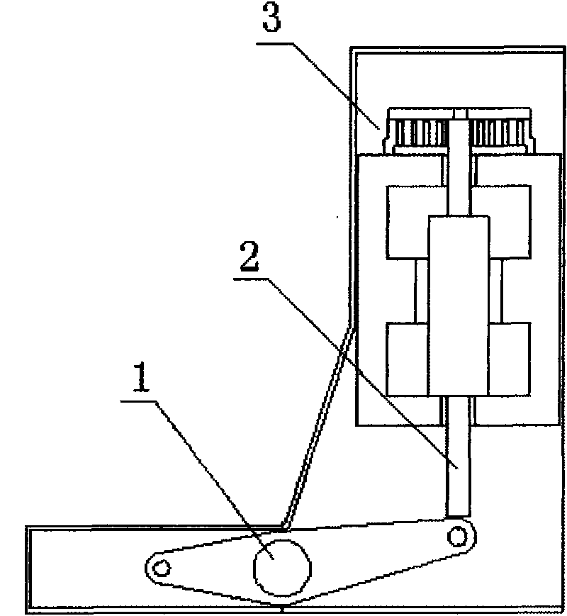
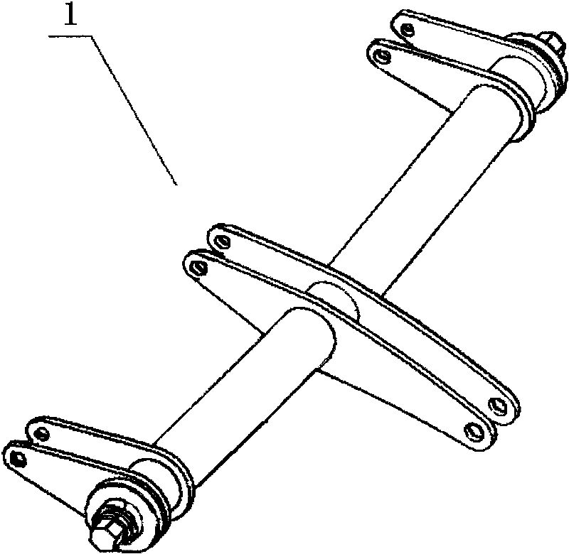
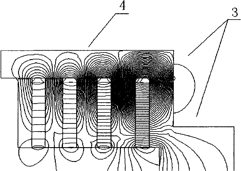
[0023] refer to figure 1 and image 3 , the permanent magnet operating mechanism for 50kA vacuum circuit breaker, compared with the traditional 50kA circuit breaker, has a similar structure, including the main shaft 1, the transmission mechanism 2, the permanent magnet mechanism, the holding module 3, and the holding module 3. Magnetic steel 4. The holding module 3 is provided with a magnetic steel shell.

[0024] refer to image 3 , the difference is that the holding module 3 of the present invention adopts a multi-ring...


PUM


Abstract

The invention relates to an operating mechanism, and in particular designs a permanent magnet operating mechanism for a circuit breaker. The permanent magnet operating mechanism for a 50 kA vacuum circuit breaker comprises a main shaft, a transmission mechanism, a permanent magnet mechanism, a holding module and magnet steel which is matched with the holding module, wherein the holding module comprises a magnet steel shell. The permanent magnet operating mechanism is characterized in that the holding module adopts a multi-ring and multi-magnetic pole structure; and the multi-ring and multi-magnetic pole structure comprises a plurality of magnetic rings with different diameters, and the magnetic rings are arranged sequentially by taking a central shaft of the magnet steel shell as a center to form the multi-ring and multi-magnetic pole structure. The permanent magnet operating mechanism has the characteristics of big holding force at an on-position, little operation power of the permanent magnet operating mechanism, good compatibility, reliable performance and the like.

Description

technical field [0001] The invention relates to an operating mechanism, in particular to a permanent magnet operating mechanism of a circuit breaker. Background technique [0002] Compared with the 31.5kA circuit breaker, the design of the 50kA circuit breaker is not as simple as increasing the holding force as commonly understood. There are many difficulties in the actual design. The problems existing on the 31.5kA mechanism will be further amplified on the 50kA mechanism, causing the circuit breaker It can not operate normally, resulting in unsolvable problems, such as a large increase in closing and opening current and operating power, the moving iron core of the mechanism stops to the so-called intermediate state, manual opening is unstable, and so on. The key and difficult problem of solving the above problems is that the design of the permanent magnet operating mechanism is not ideal enough. [0003] Among the existing 50kA circuit breakers, Senyuan VSm is more repres...

Claims


Application Information

Patent Timeline
Patent Type & Authority Applications(China)
IPC IPC(8): H01H33/666H01H33/38
Inventor 包少华吴春晖
Owner 上海安奕极企业发展股份有限公司
Why Eureka
Try Eureka