
Power source control circuit capable of changing pulse transmission power and control method

A technology of pulse transmission and power control, applied in the direction of conversion equipment without intermediate conversion to AC, can solve the problems of output power control, continuous variable power supply voltage of the transmission circuit, etc., achieve variable amplitude, reduce complexity, control flexible effects

Inactive Publication Date: 2010-05-19
HARBIN ENG UNIV
View PDF0 Cites 0 Cited by
  • Summary
  • Abstract
  • Description
  • Claims
  • Application Information

AI Technical Summary

Problems solved by technology

[0004] The purpose of the present invention is to provide a power supply control circuit that can solve the problem of continuously variable power supply voltage of the transmitting circuit, thereby solving the problem of output power control of the class D power amplifier.

Method used


Image

  • Power source control circuit capable of changing pulse transmission power and control method
  • Power source control circuit capable of changing pulse transmission power and control method
  • Power source control circuit capable of changing pulse transmission power and control method

Examples


Embodiment Construction

[0016] The present invention is described in more detail below in conjunction with accompanying drawing example:

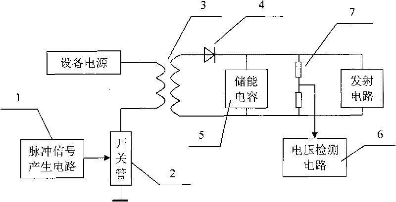
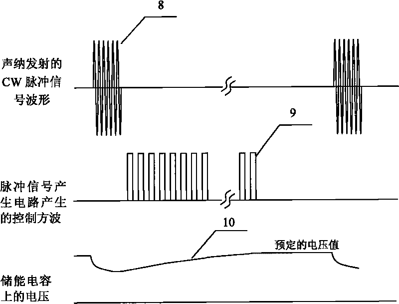
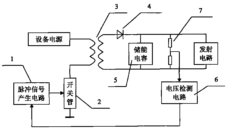
[0017] combine figure 1 and figure 2 , The composition of the controllable charging power supply circuit is mainly composed of a pulse signal generating circuit 1, a switch tube 2, a power transformer 3, a rectifier tube 4, an energy storage capacitor 5, a voltage detection circuit 6 and a voltage dividing resistor 7. Among them, the output of the pulse signal generating circuit 1 is connected to the gate of the switch tube 2; the primary end of the power transformer 3 is connected to the drain of the switch tube 2, and the other end is connected to the equipment power supply; the secondary of the power transformer is connected to the rectifier diode 4 It is connected with the energy storage capacitor 5 in turn by electrical signals; the voltage detection circuit 6 is connected to both ends of the energy storage capacitor through the voltage dividing resistor 7;...


PUM


Abstract

The invention provides a power source control circuit capable of changing pulse transmitting power and a control method. The power supply voltage value can be determined according to the output power; a pulse signal generation circuit generates a power source control signal which controls the switching state of a switching tube and has fixed frequency after finishing pulse transmitting; the power source control signal is converted into a signal with certain power and certain voltage through the switching tube and a power transformer and charges an energy storage capacitor through a rectifier diode; meanwhile, a voltage detection circuit detects the voltage at two ends of the energy storage capacitor through divider resistance; and when the voltage reaches the preset voltage value, the pulse signal generation circuit stops generating signals and outputs a low level, so that the switching tube is cut off and then the energy storage capacitor keeps the voltage until next transmission. The invention is suitable for transmitting circuits of various pulse signals, especially for the condition that low-power power source instantly generates high power, and the invention is also suitable to a transmitting circuit of continuous signals after charging current is increased.

Description

technical field [0001] The invention relates to a power control circuit, and the invention also relates to a power control method. Specifically, it is a power supply control circuit and control method capable of changing the pulse transmission power. Background technique [0002] In sonar devices, the size and power consumption of the device are often limited. In order to make the equipment have the characteristics of low power consumption, high efficiency, and small size, most sonar equipment uses Class D power amplifiers as the transmitting circuit. There are generally two ways to control the output power of the class D power amplifier. One is the pulse modulation (PWM) technology commonly used at present, the other is to change the power supply voltage, and the third is to use the transformer tap method. The use of PWM technology to control the output power has little meaning for transmitting CW pulses, linear frequency modulation (LFM) pulses and various binary coded p...

Claims


Application Information

Patent Timeline
Patent Type & Authority Applications(China)
IPC IPC(8): H02M3/07
Inventor 卢逢春孙大军曹忠义滕婷婷勇俊
Owner HARBIN ENG UNIV
Learn More