Communication system and method for wirelessly exchanging user data with a user terminal

A technology of user data and communication system, applied in the field of wireless communication system

Inactive Publication Date: 2010-05-19
KONINK KPN NV +1
View PDF0 Cites 0 Cited by
  • Summary
  • Abstract
  • Description
  • Claims
  • Application Information

AI Technical Summary

Problems solved by technology

However, the above-mentioned problems of the data connection of the wireless access station are also encountered for such a communication system

Method used


Image

  • Communication system and method for wirelessly exchanging user data with a user terminal
  • Communication system and method for wirelessly exchanging user data with a user terminal
  • Communication system and method for wirelessly exchanging user data with a user terminal

Examples


Embodiment Construction

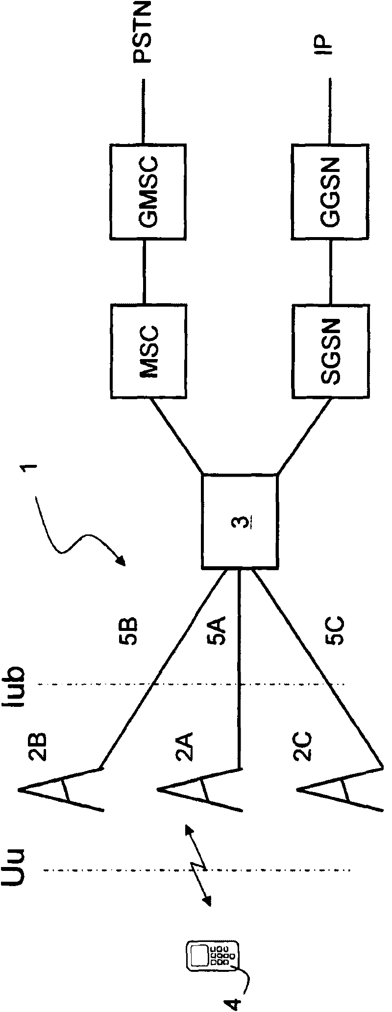
[0040] Figure 1A is a schematic diagram of the UMTS communication system 1 . The UMTS communication system 1 comprises a radio access network with a plurality of radio access stations 2A, 2B, 2C and a radio network controller 3 . Below, for Figure 1A system, the wireless access stations 2A-2C are referred to as Node B, and the controller 3 is abbreviated as RNC (Radio Network Controller).

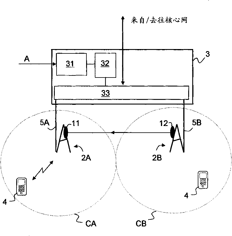
[0041] Node B 2A-2C by defining and supporting one or more cells (see figure 2 ) to provide wireless access for user terminals 4 (also referred to as user equipment UE). The wireless interface between UE 4 and Node B 2A is called Uu interface.

[0042] Each Node B 2A-2C has a corresponding data connection 5A-5C to the RNC 3 of the radio access network. The interface between Node B and RNC is called Iub interface. Data connections 5A-5C may include one or more connections (wired and / or wireless) with constrained data transmission capacity. Data transfer via the Iub interface can be e...


PUM


Abstract

The invention relates to a communication system and a method for wirelessly exchanging user data with a user terminal. The communication system comprises a first wireless access station with a first data connection for transferring user data and a second wireless access station with a second data connection for transferring user data. The first wireless access station and second wireless access station are located at distant positions from each other. The first wireless access station comprises one or more antennas for wirelessly transmitting user data, that are received over the first data connection, to a user terminal. The second wireless access station is configured to receive user data over the second data connection and to transmit the user data directly to the first wireless access station for transmission to the user terminal. The communication system further comprises a controller configured for controlling at least a part of the user data for the user terminal to flow over the second data connection.

Description

technical field [0001] The present invention relates to the field of wireless communication systems. In particular, the present invention relates to communication systems and methods for wirelessly exchanging user data with user terminals. Background technique [0002] Wireless communication systems enable user data to be exchanged wirelessly between wireless access stations (also called base stations) and user terminals. The user terminal may be a mobile user terminal accessing the wireless communication system, and is used to receive user data from the base station and send user data to the base station. [0003] A wireless communication system typically includes a radio access network and a core network. For UMTS communication systems, details are provided in 3GGP 23.002. [0004] Typically, for UMTS radio access networks, the base stations are referred to as Node Bs. A Node B provides radio access to the core network for user terminals (also referred to as user equip...

Claims


Application Information

Patent Timeline
Patent Type & Authority Applications(China)
IPC IPC(8): H04W28/02H04W92/04
CPCH04L47/14H04W92/20H04W28/0247H04W28/08H04W28/02H04W8/04
Inventor J·C·范德瓦尔N·A·S·古斯塔夫森L·乔古塞斯基
Owner KONINK KPN NV
Why Eureka
Try Eureka