Magnetic resonance diagnostic apparatus and magnetic resonance diagnostic method

A diagnostic device, magnetic resonance technology, applied in the direction of diagnosis, diagnostic recording/measurement, medical science, etc., can solve problems such as deterioration, larger motion artifacts, and higher costs

Active Publication Date: 2012-11-28
TOSHIBA MEDICAL SYST CORP
View PDF3 Cites 0 Cited by
  • Summary
  • Abstract
  • Description
  • Claims
  • Application Information

AI Technical Summary

Problems solved by technology

However, when the MPG pulse application time δ is increased to increase the b value, the TE (echo time) is prolonged, so the SNR (signal-to-noise ratio, signal-to-noise ratio) deteriorates and motion artifacts become larger
When increasing the maximum gradient magnetic field strength G to obtain a large b value while keeping TE constant, it is necessary to improve the performance of the hardware of the gradient magnetic field system, which increases the cost

Method used


Image

  • Magnetic resonance diagnostic apparatus and magnetic resonance diagnostic method
  • Magnetic resonance diagnostic apparatus and magnetic resonance diagnostic method
  • Magnetic resonance diagnostic apparatus and magnetic resonance diagnostic method

Examples


no. 1 Embodiment approach

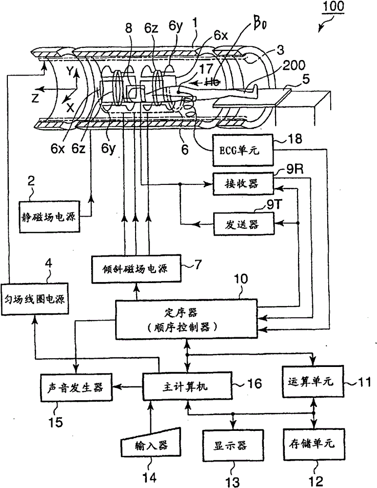
[0053] Hereinafter, the operation in the first embodiment of the magnetic resonance diagnostic apparatus 100 will be described.

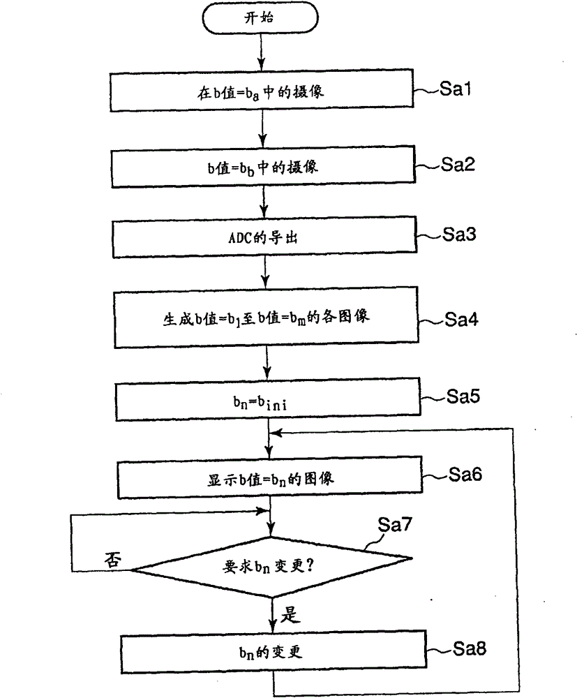
[0054] figure 2 It is a flowchart showing the processing procedure in the first embodiment of the host computer 16 .

[0055] In step Sa1, the host computer 16 sends an instruction to the sequencer 10 to set the b value to the preset value b for the preset region of interest. a camera. The sequencer 10 operates the gradient magnetic field power supply 7, the transmitter 9T, the receiver 9R, and the arithmetic unit 11 according to the instruction, so that the operation using the held value b a The b-value of the camera. Hereinafter, the image captured here will be referred to as a first original image.

[0056] Additionally, the value b a It can be any value, but it is better to take 0. in b a When =0, T2-enhanced imaging using the SE (spin echo: spin echo) method or the FSE (fast spin echo: fast spin echo) method can be used for the imaging ...

no. 2 Embodiment approach

[0077] The operation of the second embodiment of the magnetic resonance diagnostic apparatus 100 will be described below.

[0078] Figure 6 It is a flowchart showing the processing procedure of the second embodiment of the host computer 16 . In addition, in the same figure 2 The same symbols are assigned to the same processes, and detailed description thereof will be omitted.

[0079] In step Sb1 , the host computer 16 determines which part of the subject the part to be imaged from now on (hereinafter referred to as an imaging part) is. The determination of the imaging site can be performed based on user designation input via the input unit 14, for example.

[0080] In step Sb2, the host computer 16 sends an instruction to the sequencer 10 to set the b value to the set value b related to the imaging site for the preset region of interest. a camera. The sequencer 10 activates the gradient magnetic field power supply 7, the transmitter 9T, the receiver 9R, and the arithme...

no. 3 Embodiment approach

[0098] The operation of the third embodiment of the magnetic resonance diagnostic apparatus 100 will be described below.

[0099] Figure 8 It is a flowchart showing the processing procedure of the third embodiment of the host computer 16 . In addition, in the same figure 2 The same symbols are assigned to the same processes, and detailed description thereof will be omitted.

[0100] The host computer 16 first captures the first original image in step Sa1 in the same manner as in the first embodiment, and then proceeds to step Sc1.

[0101] In step Sc1, the host computer 16 determines the imaging site, and acquires the diffusion coefficient D related to the imaging site. Diffusion coefficients vary for anatomical tissues in the human body, and standard diffusion coefficients are known for normal tissues. Therefore, pre-set as Figure 9 The shown information tables are stored in the storage unit 12 in association with the anatomical tissues that may serve as imaging sites...


PUM


Abstract

A host computer 16 derives an apparent diffusion coefficient regarding a pixel position for each pixel position included in a region of interest in at least two original images obtained by imaging a same imaging region of a same subject using at least two b-factors which are different from each other, respectively, based on pixel values of each of at least two original images regarding the pixel positions, and estimates a pixel value obtained by using a b-factor which is different from the at least two b-factors, regarding each pixel position included in the region of interest, based on the apparent diffusion coefficient derived for each pixel position.

Description

[0001] Cross References to Related Applications [0002] This application is based on and claims priority from prior Japanese Patent Application No. 2008-251683 filed on September 29, 2008, the entire contents of which are incorporated herein by reference. technical field [0003] The present invention relates to a magnetic resonance diagnostic apparatus and a magnetic resonance diagnostic method for obtaining an image of a subject by using a magnetic resonance phenomenon. Background technique [0004] In diffusion weighted imaging (DWI), a pair of diffusion detection gradient magnetic fields (motion probing gradient: MPG) are added during imaging. And, during MPG application, a diffusion-enhanced image is acquired by imaging a signal difference that occurs depending on the degree of spin phase dispersion of protons that move due to diffusion. [0005] The b value (b-factor) is used as a value indicating the magnitude of the influence of the MPG pulse. Increasing the b val...

Claims


Application Information

Patent Timeline
Patent Type & Authority Patents(China)
IPC IPC(8): A61B5/055
Inventor 杉浦聪木村德典镰田光和
Owner TOSHIBA MEDICAL SYST CORP
Why Eureka
Try Eureka