
Steel rail rolling method

A technology of rail and rough rolling, applied in the field of rail rolling, can solve the problems of uneven wear degree of rolls, reduce production efficiency, serious roll wear, etc., and achieve the effect of shortening the development cycle and improving the success rate of development.

Inactive Publication Date: 2010-05-26
PANGANG GROUP VANADIUM TITANIUM & RESOURCES +1
View PDF0 Cites 11 Cited by
  • Summary
  • Abstract
  • Description
  • Claims
  • Application Information

AI Technical Summary

Problems solved by technology

However, the smaller-sized rail pilot hole and the universal rough-rolling hole have a relatively large abdominal cavity slope. During the rolling process, the rolls on the abdominal cavity slope part of the pass are severely worn, the wear degree of the rolls is uneven, and the shape of the pass is destroyed. This is difficult. Guarantee the specifications of rolled pieces
In actual production, it is also found that after the rolls are subjected to uneven wear, those slope parts with more serious wear reduce the processing ability of the rolled piece, and the surface of the rolled piece is easy to stick to the oxide scale, which affects the surface quality of the rolled piece
The difference in the slope of the pass is large, and the wear of the roll is serious, which reduces the service life of the roll, increases the frequency of roll change, and reduces the production efficiency
[0016] 4. Restrictions on the bite conditions of the rolled piece

Method used


Image

  • Steel rail rolling method
  • Steel rail rolling method
  • Steel rail rolling method

Examples


Embodiment

[0050] The production specifications of a factory (bottom width×rail height×abdominal width×waist thickness, unit of size) are GB60 (150×176×97×16.5, mm),

[0051] UIC60 (150×172×89.5×16.5, mm),

[0052] 136RE (152.4×185.74×106.36×17.46, mm),

[0053] 115RE (139.7×168.3×96.84×15.88, mm),

[0054] GB75 (150×192×104.4×20, mm)

[0055] The five kinds of rails of the present invention adopt the rail rolling method of the present invention, that is, the rolling process in the BD area is designed with GB60 as the standard, and the remaining four varieties are applied to the rolling process in the BD area of ​​the GB60 rail, and the specifications and sizes of each variety produced are It fully complied with the requirements of the standard, and the abdominal cavity was filled well. At the same time, there were no folding defects at the joints of the legs and waist, and the joints of the head and waist.


PUM


Abstract

The invention discloses a steel rail rolling method capable of shortening the development cycle of a new species. The method comprises a rolling process of a BD area and a rolling process of a universal area. The last hole pattern of the BD area is a pilot hole, and the first hole pattern of the universal area is a universal coarse rolling hole. For steel rails in a specification of 43-75kg / m, the following parameter range of the same BD area for rolling the steel rails is applied: the rail bottom width difference delta D is smaller than or equal to 15mm, the waist thickness difference delta E is smaller than or equal to 5mm, and the rail height difference delta C is smaller than or equal to 25mm. The hole pattern transition from the pilot hole to the universal coarse rolling hole meets the following requirements: the abdominal cavity widening width L is -3-+5mm; the radius difference delta R of a leg and waist connecting arc and a head and waist connecting arc is smaller than or equal to 10mm; for a leg-inside single-inclination steel rail, the difference of the leg-inside inclination of the pilot hole and the leg-inside inclination of the universal coarse rolling hole is 5-8 degrees; and for a leg-inside double-inclination steel rail, the difference of the leg-inside inclination of the pilot hole and the leg-inside inclination of the universal coarse rolling hole is 3-6 degrees. The development cycle of products can be greatly shortened, the development time of a new product can be shortened by about 2 / 3, and the development success ratio can be improved by one time, thus the method can be applied to the steel rails of a specification of 43-75kg / m.

Description

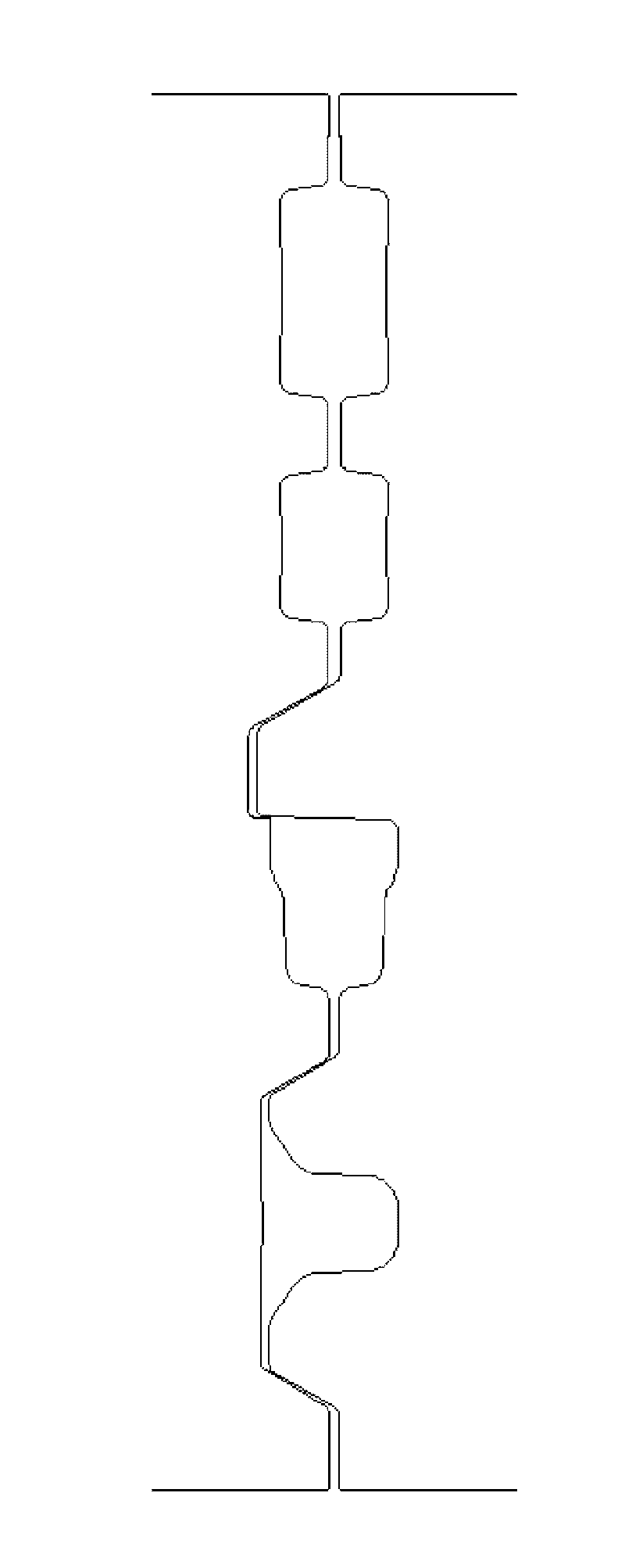
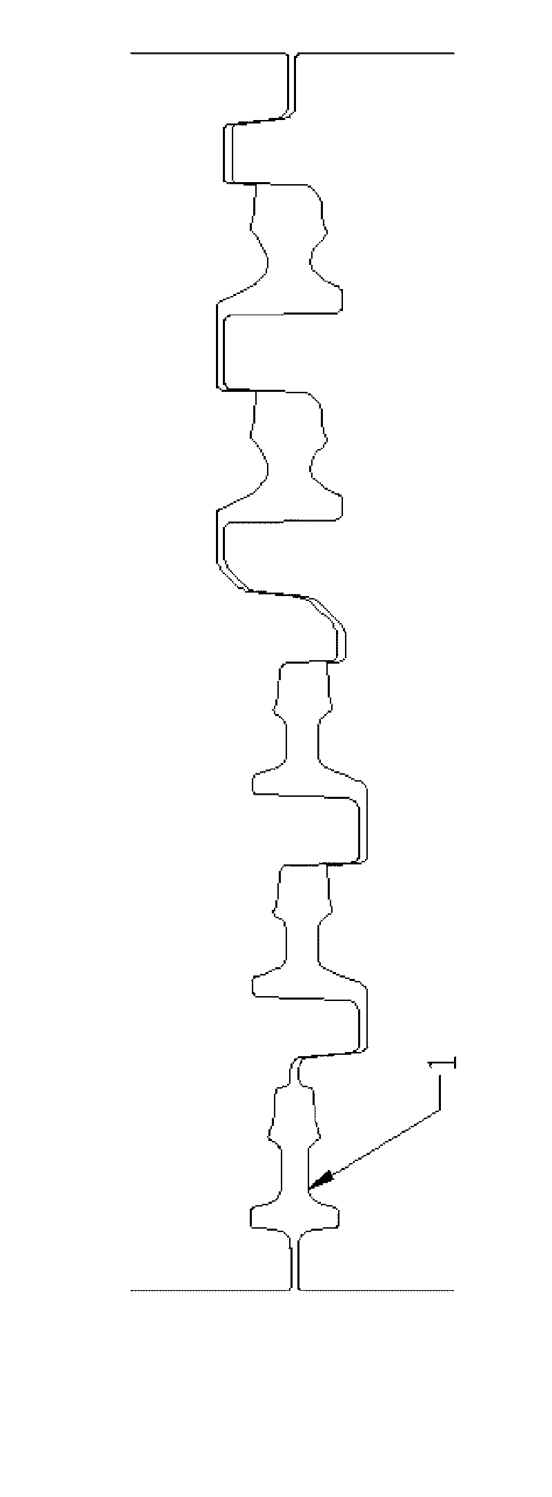
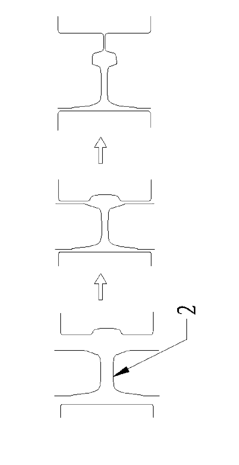
technical field [0001] The invention relates to the field of steel rolling, in particular to a rail rolling method. Background technique [0002] At present, modern rail production enterprises generally adopt the world's advanced and mature universal rolling production mode with seven or five racks separated. The rolling production line is composed of BD area and universal area. BD area is composed of BD1 and BD2 units Composition, the universal tandem rolling mill consists of a universal roughing mill, an edge mill and a finishing mill. [0003] The roll system of the rail BD unit is composed of upper and lower horizontal rolls, and adopts the direct rolling method. The pass shape of the BD area is as follows: figure 1 and figure 2 shown. [0004] The roll system of the rail universal rolling mill consists of upper and lower horizontal rolls and two vertical rolls on the transmission side and the operation side to form a universal rough rolling pass. The pass in the uni...

Claims


Application Information

Patent Timeline
IPC IPC(8): B21B1/085B21B37/16
Inventor 陶功明王彦中马朝辉林刚程铖
Owner PANGANG GROUP VANADIUM TITANIUM & RESOURCES
Learn More