
Underground hole-forming device of hydraulic grab bucket

A technology of hole forming device and hydraulic grab bucket, which is applied in the direction of earth mover/shovel, construction, etc., can solve the problems of slow construction progress, hidden dangers, huge equipment, etc., and achieves a high degree of mechanization, strong adaptability, and processing capacity. less effect

Inactive Publication Date: 2011-06-29
曹蓝天
View PDF0 Cites 0 Cited by
  • Summary
  • Abstract
  • Description
  • Claims
  • Application Information

AI Technical Summary

Problems solved by technology

[0003] The present invention is based on the above-mentioned existing underground pore-forming methods. In actual pore-forming, especially when encountering hard soil or rock formations, some have potential safety hazards, slow construction progress, some have unreasonable structures and poor adaptability, and some have sludge treatment To solve the problems of large quantity, huge equipment, low efficiency, etc., provide a hydraulic grab underground hole-forming device with high mechanization, low cost, high efficiency, strong adaptability, less sludge treatment, and safety.

Method used


Image

  • Underground hole-forming device of hydraulic grab bucket
  • Underground hole-forming device of hydraulic grab bucket
  • Underground hole-forming device of hydraulic grab bucket

Examples


Embodiment Construction

[0029] The present invention will be further described in detail below in conjunction with the accompanying drawings and embodiments, and this embodiment will further describe the present invention in detail without any limitation to the present invention.

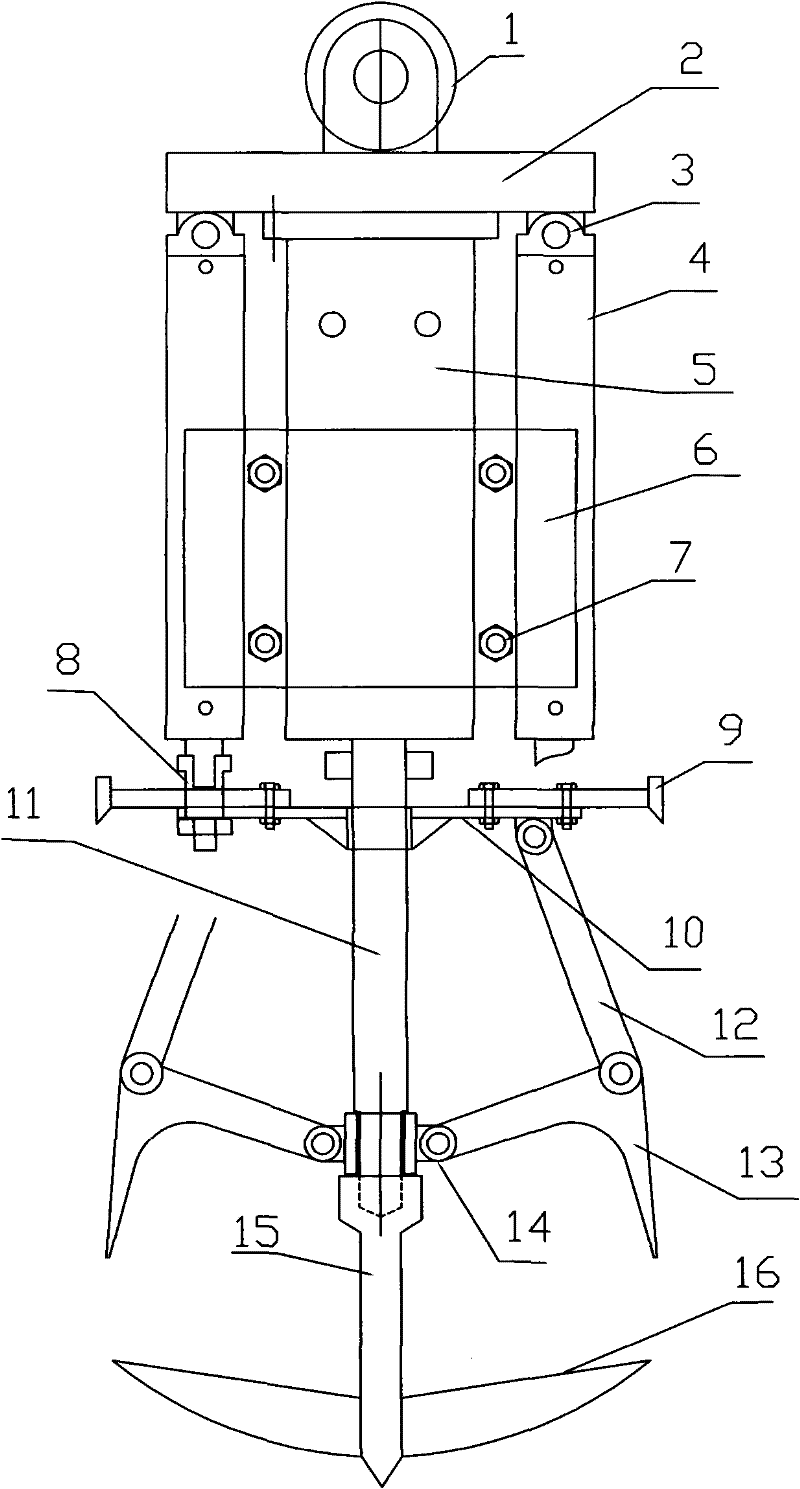
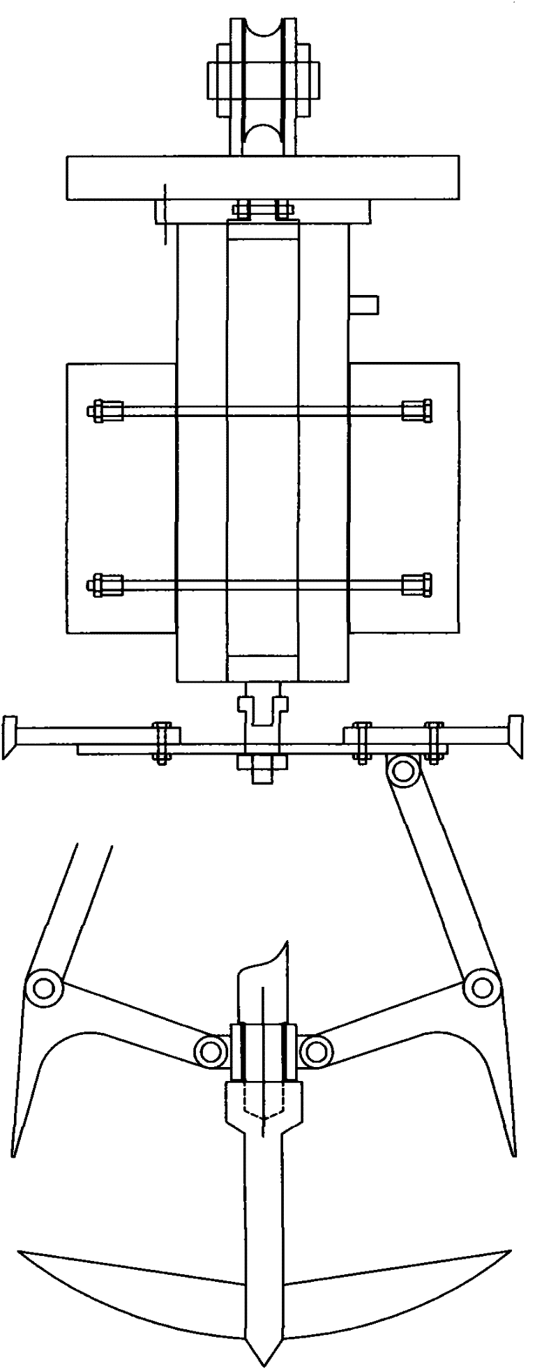
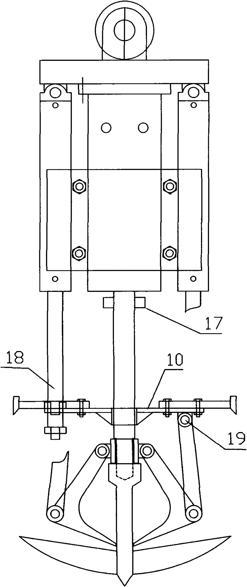
[0030] The present invention mainly consists of wire rope pulley 1, top support plate 2, hydraulic jack connecting pin 3, hydraulic jack 4, breaking hammer 5, counterweight 6, counterweight fixing bolt 7, hydraulic jack and grab tray connector 8, hole reamer 9. Grab tray 10, hydraulic crushing drill upper rod 11, grab support rod 12, grab flap 13, grab connecting rod center sleeve 14, hydraulic crushing drill lower rod 15, cutter head 16, hydraulic crushing drill upper rod sleeve 17 , Hydraulic jack lifter 18, grab tray and grab support rod connection pin hole 19, top support plate connection hole 20, grab tray center sleeve 21, reamer installation hole 22, connector through hole 23, breaker oil Road interface 24, connecto...


PUM


Abstract

The invention discloses an underground hole-forming device of a hydraulic grab bucket. The device is characterized in that a wire rope pulley is arranged above a top support plate; a hydraulic jack and a hydraulic breaking hammer are arranged below the top support plate; a grab bucket is arranged below the hydraulic breaking hammer; and a tool bit is arranged on a hydraulic crushing bit. With thehelp of hydraulic power on the ground and lifting equipment, the aim of crushing and lifting subsurface soil, sand, rock and other underground objects is achieved. Underground rock layers are crushedby using strong impact of the hydraulic breaking hammer and materials are grabbed by using strong power of the hydraulic jack. The problem that rotary digging machines and other grab bucket hole-forming machines difficultly enter rocks or cannot enter rocks is solved. An underground hole-forming device of the hydraulic grab bucket, which has the advantages of high mechanization degree, low manufacturing cost, high efficiency, strong adaptability, less sludge treatment capacity, and safety and reliability, is realized.

Description

technical field [0001] The invention relates to a hole-forming device for building pile foundation construction, in particular to an underground hole-forming device which impacts with a hydraulic breaker and grabs sludge with a hydraulic grab bucket. Background technique [0002] In the design and construction of domestic and foreign construction projects, most of the foundation treatment adopts cast-in-situ pile foundation, such as: the foundation of high-rise buildings, bridges, ports, and large-scale equipment. With the increase of building requirements for foundation load, designers have designed a variety of pile types according to geological conditions. Low-socketed piles of end-bearing piles are a good way to increase the load of single piles and reduce foundation sinking. In order to ensure the quality of cast-in-situ piles, not only the pile body can meet the strength requirements, but also the integrity of the pile body is required. In the construction of cast-in-...

Claims


Application Information

Patent Timeline
Patent Type & Authority Patents(China)
IPC IPC(8): E02F5/20E02F5/30
Inventor 曹蓝天
Owner 曹蓝天
Learn More